Folding antenna high-precision deployment control method based on motor current feedback

A technology of folding antenna and control method, which is applied to electromechanical devices, control mechanical energy, electrical components, etc., can solve the problems of low precision of angle measuring components, unable to maintain a stable state of antenna profile, low profile precision, etc., to ensure positioning accuracy. and repeatability, eliminate the structural transmission gap, improve the effect of rigidity

Inactive Publication Date: 2018-01-09
THE 724TH RES INST OF CHINA SHIPBUILDING IND
View PDF4 Cites 3 Cited by
  • Summary
  • Abstract
  • Description
  • Claims
  • Application Information

AI Technical Summary

Problems solved by technology

Adopting this control method is simple and easy to implement, but the deployment accuracy of the antenna is easily affected by the accuracy of the detection switch, the installation position of the detection switch, etc., and the surface accuracy of the antenna after deployment is low
Adopting the control method of detecting the position of the angle measuring element, although the position (angle) of the antenna can be detected intuitively, but the accuracy of some angle measuring elements is low, which cannot meet the accuracy requirements of the profile; in addition, some high-precision angle measuring elements are large in size , the general folded antenna has a compact structure, and there is not enough installation space or a suitable location to install such goniometer elements
Therefore, the above two detection and control methods all have their disadvantages or use limitations.
In addition, the folding antenna is generally fixed and connected by a rotating hinge, a reduction box, and a transmission screw. It is not a stable rigid body. The above two in-position control methods are adopted. Under the antenna rotation state or under the influence of wind load, the antenna profile cannot remain in a steady state

Method used


Image

  • Folding antenna high-precision deployment control method based on motor current feedback
  • Folding antenna high-precision deployment control method based on motor current feedback
  • Folding antenna high-precision deployment control method based on motor current feedback

Examples


Embodiment Construction

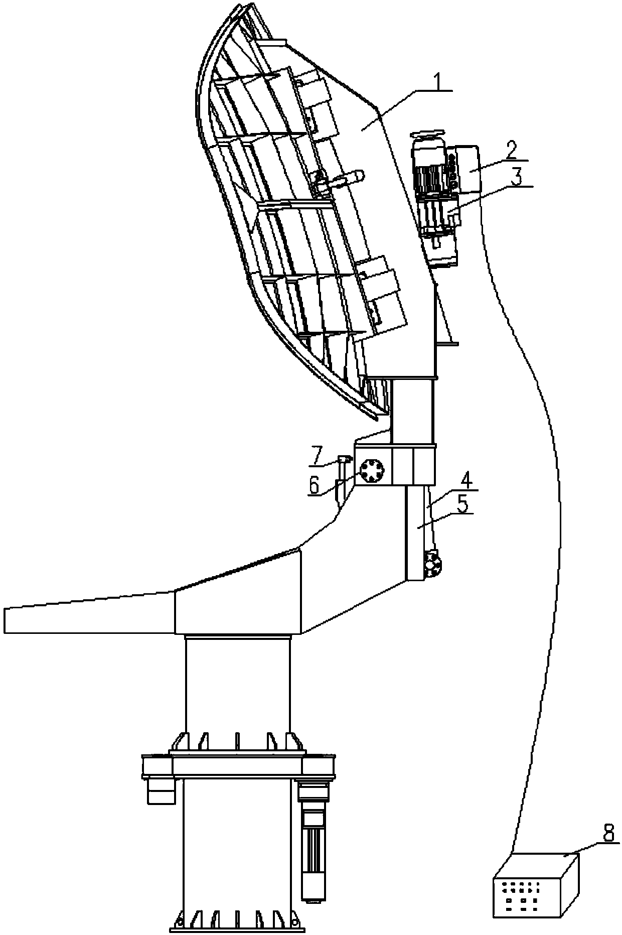
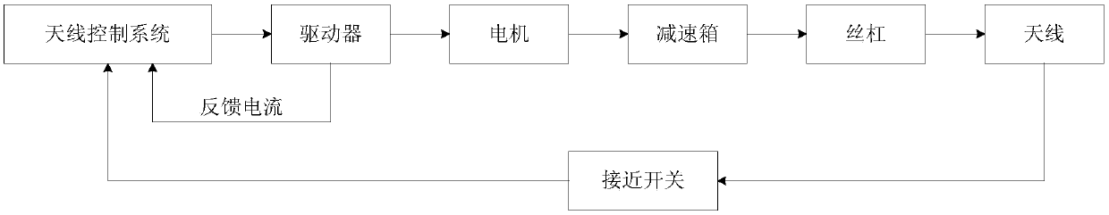
[0014] According to the vehicle transportation width limit, height limit, and vehicle platform installation space, layout and other requirements, the antenna is divided into reasonable blocks. Each sub-block is connected by a rotary hinge, and the reduction box is driven by a motor to drive the trapezoidal screw to move in a straight line, so that the sub-blocks rotate around the rotary hinge to realize the unfolding and collapsing of the antenna sub-blocks.

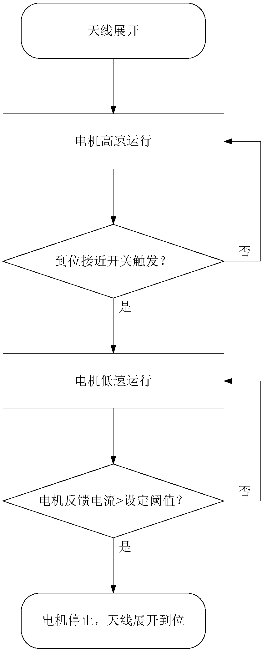
[0015] Proximity switches are designed and installed where each antenna block is about to be put in place, and high-strength and rigid mechanical stops are designed and installed at the precise location. The mechanical stopper directly affects the accuracy of the antenna’s in-position profile, so precision machining should be adopted to meet the requirements, and the installation position of the stopper should be repeatedly confirmed by corresponding tooling or laser tracker and other instruments. The selected motor shou...


PUM


Abstract

The invention relates to a folding antenna high-precision deployment control method based on motor current feedback, which belongs to the field of electromechanical integrated control. The method is designed to solve the problem that the precision of automatic deployment of the folding antenna is low and the folding antenna is of poor rigidity. In view of the problem, the control method as followsis adopted: a proximity switch is designed and installed in a position where an antenna is about to be deployed in place; a mechanical block with high strength and stiffness is set in the precise position; after a control system receives an antenna deployment operation instruction, a motor runs at high speed, and a reducer box drives a trapezoidal screw to drive an antenna block to be deployed; after the in-place proximity switch is triggered, the running speed of the motor is reduced, the motor continues to run at low speed after contacting the mechanical block, and thus, the structure gap is eliminated; and a pre-tightening force is applied to the antenna structure, the feedback current of the motor is detected, and when the feedback current of the motor rises sharply and exceeds a setthreshold, that the antenna is deployed in place is determined, and the motor is immediately disabled. Through the method, antennas can be precisely deployed in place, and the rigidity of antennas isimproved.

Description

technical field [0001] The invention belongs to the field of electromechanical integration control, and relates to a control method for unfolding a folding antenna in place. Background technique [0002] In order to ensure its road and railway passability, the large-diameter antenna is usually designed as a foldable structure. There are two main technical problems in the design and use of folding antennas that need to be solved: one is how to ensure that the surface accuracy of the folding antenna after it is automatically unfolded in place meets the requirements of radar use; the other is that folding antennas often use structural parts such as transmission mechanisms and rotating hinges To realize the unfolding or folding action, there is a structural gap inside the transmission mechanism and the rotating hinge. When the antenna is in the working rotation state or under the wind load, the magnitude and direction of the force will change, which will cause the structural par...

Claims


Application Information

Patent Timeline
Patent Type & Authority Applications(China)
IPC IPC(8): G01S7/02G01S7/40H02K7/10
Inventor 张伟王宏杰张杰施永柱
Owner THE 724TH RES INST OF CHINA SHIPBUILDING IND
Why Eureka
Try Eureka