Optical module

An optical module and optical fiber technology, applied in the field of optical fiber communication, can solve the problems of difficult multi-channel beam coupling, difficult to achieve multiple beam transmission, etc.

Active Publication Date: 2018-01-09
HISENSE BROADBAND MULTIMEDIA TECH
View PDF3 Cites 2 Cited by
  • Summary
  • Abstract
  • Description
  • Claims
  • Application Information

AI Technical Summary

Problems solved by technology

[0003] However, it is difficult for the lenses in the market to realize the coupling of multi-channel beams, and it is difficult to achieve the simultaneous transmission of multiple beams along the direction of the optical fiber port.

Method used


Image

  • Optical module
  • Optical module
  • Optical module

Examples


Embodiment Construction

[0021] The implementation process of the embodiment of the present invention will be described in detail below in conjunction with the accompanying drawings. It should be noted that the same or similar reference numerals represent the same or similar elements or elements having the same or similar functions throughout. The embodiments described below by referring to the figures are exemplary only for explaining the present invention and should not be construed as limiting the present invention.

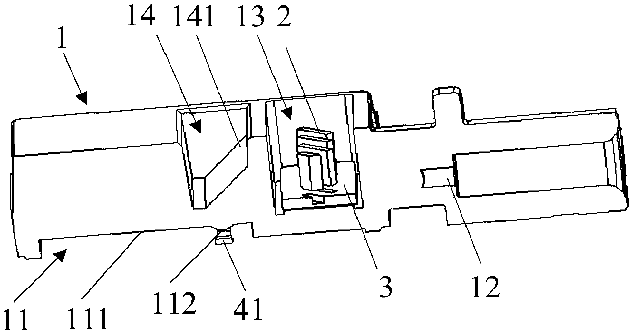
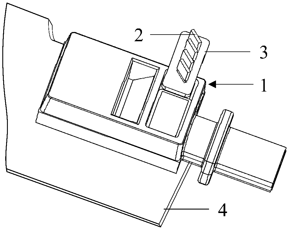
[0022] Such as figure 1 and figure 2 as shown, figure 1 is a cross-section diagram of the optical module, figure 2 It is a schematic diagram of a circuit board in an optical module. The optical module provided by the embodiment of the present invention includes a lens body 1, an optical filter group 2, a plurality of lasers 41, and a circuit board 4. The lasers 41 and optical chips are installed on the circuit board 4, and the optical filter The sheet group 2 includes optical fi...


PUM


Abstract

The invention relates to the technical field of optical fiber communication, and discloses an optical module. The optical module comprises a lens body, a optical filter group, a plurality of lasers and a circuit board. The lasers are arranged on the circuit board. The optical filter group comprises optical filters corresponding to optical filter units in the one-to-one correspondence mode. A chipcavity is formed in the lens body. A laser light incident surface is formed in the bottom surface of the chip cavity. The lasers are arranged in the chip cavity. The optical emitting directions of thelasers face the laser light incident surface. An optical fiber optical port is arranged at the tail end of the lens body and is used for installing an optical fiber. The optical filter group is arranged in an optical filter cavity and is used for coupling and introducing multiple optical beams irradiated to the optical filter group into the optical fiber at the optical fiber optical port. The bottom surface of a reflection cavity is used for totally reflecting light beams introduced by the laser light incident surface to the reflecting surface of the optical filter group. The above optical module is used for coupling multiple channels of optical paths. Furthermore, multiple light beams can be transmitted simultaneously along the direction of the optical fiber optical port.

Description

technical field [0001] The invention relates to the technical field of optical fiber communication, in particular to an optical module. Background technique [0002] The chip on board (COB) lens (Lens) in the optical module is manufactured by integral injection molding. When installing, it is directly mounted on the printed circuit board. This method can simply complete the lens and laser. The coupling of the electric device is convenient to operate and can reduce the cost. [0003] However, it is difficult for the lenses currently on the market to achieve coupling of multi-channel light beams, and it is difficult to achieve simultaneous transmission of multiple light beams along the direction of the optical fiber port. Contents of the invention [0004] The object of the present invention is to provide an optical module capable of coupling multi-channel optical paths, thereby realizing simultaneous transmission of multiple beams along the optical fiber port. [0005] Th...

Claims


Application Information

Patent Timeline
IPC IPC(8): G02B6/42
Inventor 刘旭霞钟岩邵乾
Owner HISENSE BROADBAND MULTIMEDIA TECH
Why Eureka
Try Eureka