Cooling components and refrigeration equipment

A technology of heat dissipation components and refrigeration equipment, which is applied in the direction of cooling/ventilation/heating transformation, etc. It can solve problems such as difficult to achieve heat dissipation, and achieve the effects of reducing contact thermal resistance, avoiding direct contact, and lowering temperature

Active Publication Date: 2020-03-27
GD MIDEA HEATING & VENTILATING EQUIP CO LTD +1
View PDF15 Cites 0 Cited by
  • Summary
  • Abstract
  • Description
  • Claims
  • Application Information

AI Technical Summary

Problems solved by technology

[0002] At present, the electric control boxes of air conditioners on the market require certain structural design to dissipate the heat generated by the heating components due to the existence of heating components inside the electric control box. Or form an air duct inside and outside the electric control box to achieve the purpose of heat dissipation. It is difficult to achieve the effect of heat dissipation when the electric control box needs to be sealed or semi-closed

Method used


Image

  • Cooling components and refrigeration equipment
  • Cooling components and refrigeration equipment
  • Cooling components and refrigeration equipment

Examples


Embodiment Construction

[0036] In order to understand the above-mentioned purpose, features and advantages of the present invention more clearly, the present invention will be further described in detail below in conjunction with the accompanying drawings and specific embodiments. It should be noted that, in the case of no conflict, the embodiments of the present application and the features in the embodiments can be combined with each other.

[0037] In the following description, many specific details are set forth in order to fully understand the present invention. However, the present invention can also be implemented in other ways different from those described here. Therefore, the protection scope of the present invention is not limited by the specific details disclosed below. EXAMPLE LIMITATIONS.

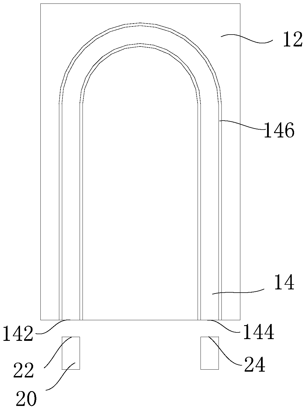
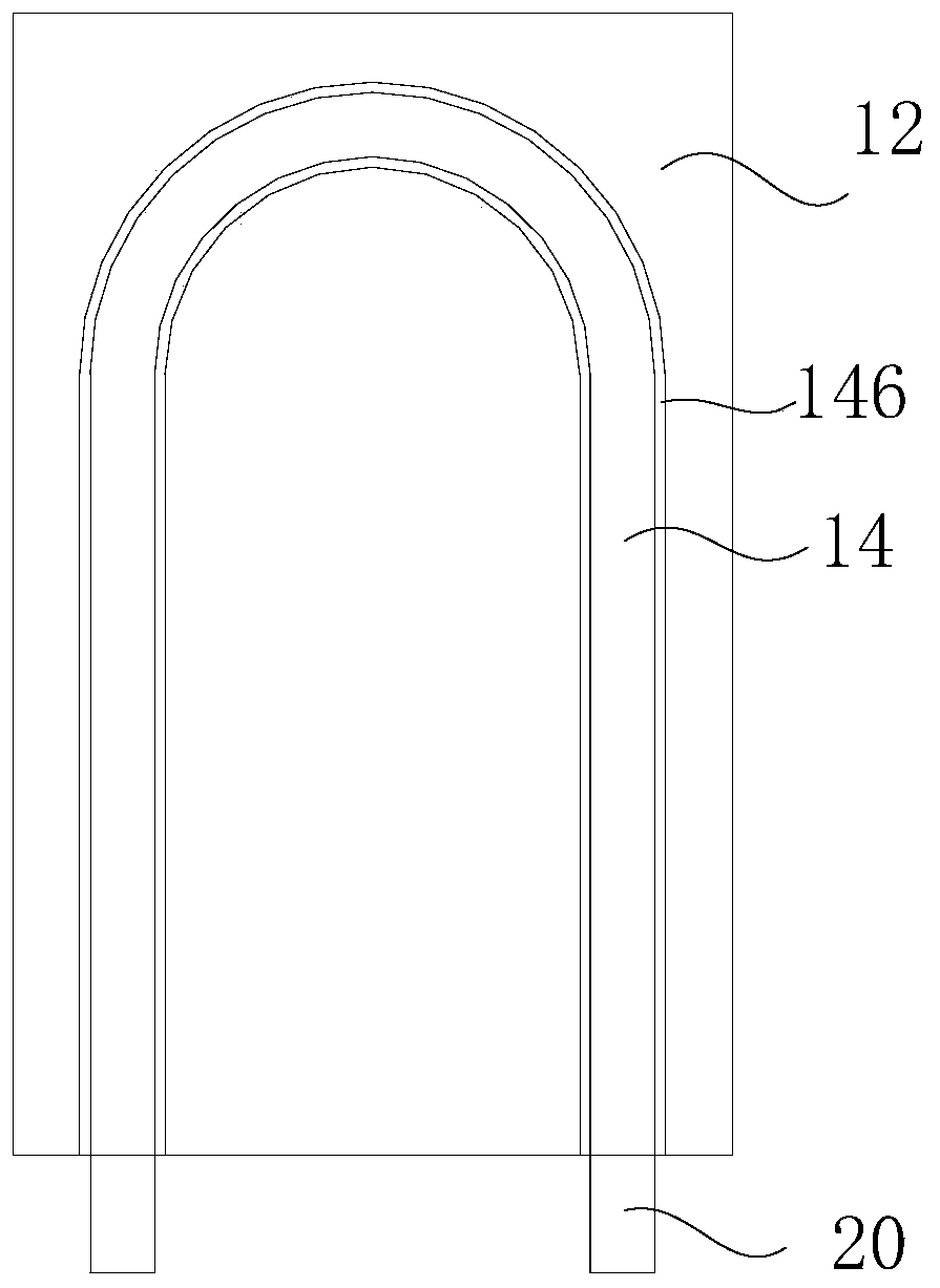
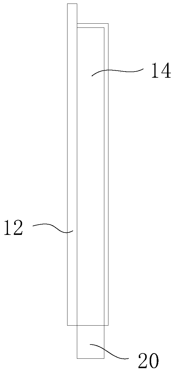
[0038] Refer below Figure 1 to Figure 4 The heat dissipation assembly according to some embodiments of the present invention is described.

[0039] Such as figure 1 , figure 2 and Figure 4 As...


PUM


Abstract

The invention provides a heat radiation assembly, having a first heat radiation plate and a second heat radiation piece. One end of the first heat radiation plate is connected to a driving chip, and the second heat radiation piece is connected to the other end of the first heat radiation plate. The heat radiation piece is a hollow structure. The end part of the second heat radiation piece is respectively provided with a refrigerant inlet and a refrigerant outlet. The refrigerant flows into the second heat radiation piece through the refrigerant inlet, and transmits low temperature to the firstheat radiation plate through the second heat radiation piece. The first heat radiation plate then transmits the low temperature to the driving chip to cool down chips. The arrangement of a copper pipe and a fixed aluminum plate for the refrigerant circulation is removed. The invention is advantageous in that the number of the heat radiation assemblies is small, contact thermal resistance is smalland heat radiation efficiency is high, and thereby the chip temperature can be effectively reduced; one end of the first heat radiation plate is connected to the driving chip, and the plate-shaped structure guarantees the connection stability and improves heat radiation efficiency, and thereby the contact failure between the copper pipe and the chip can be prevented; through the structure changeof the second heat radiation piece, the cooling demand of various chips can be met.

Description

technical field [0001] The present invention relates to the technical field of refrigeration equipment, in particular to a heat dissipation component and refrigeration equipment. Background technique [0002] At present, the electric control boxes of air conditioners on the market require certain structural design to dissipate the heat generated by the heating components due to the existence of heating components inside the electric control box. Or form an air duct inside and outside the electric control box to achieve the purpose of heat dissipation. It is difficult to achieve the effect of heat dissipation when the electric control box needs to be sealed or semi-closed. Contents of the invention [0003] The present invention aims to solve at least one of the technical problems existing in the prior art or related art. [0004] Therefore, one aspect of the present invention is to provide a heat dissipation assembly. [0005] Another aspect of the present invention is t...

Claims


Application Information

Patent Timeline
Patent Type & Authority Patents(China)
IPC IPC(8): H05K7/20
Inventor 任建华骆名文陈文强
Owner GD MIDEA HEATING & VENTILATING EQUIP CO LTD
Why Eureka
Try Eureka