
Time domain distance testing method and device

A ranging method and time-domain technology, applied in the direction of measuring devices, measuring electricity, fault locations, etc., can solve the problems of not seeing, accurately measuring single-tone signals, etc., and achieve the effects of size reduction, accurate measurement, and great practicability

Inactive Publication Date: 2018-01-12
BEIJING RINFON TECH CO LTD
View PDF7 Cites 9 Cited by
  • Summary
  • Abstract
  • Description
  • Claims
  • Application Information

AI Technical Summary

Problems solved by technology

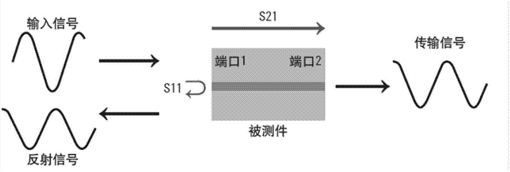
[0007] However, the prior art does not see how to accurately measure the frequency, amplitude, and phase of each single tone signal fed back in this case

Method used


Image

  • Time domain distance testing method and device
  • Time domain distance testing method and device
  • Time domain distance testing method and device

Examples


Embodiment

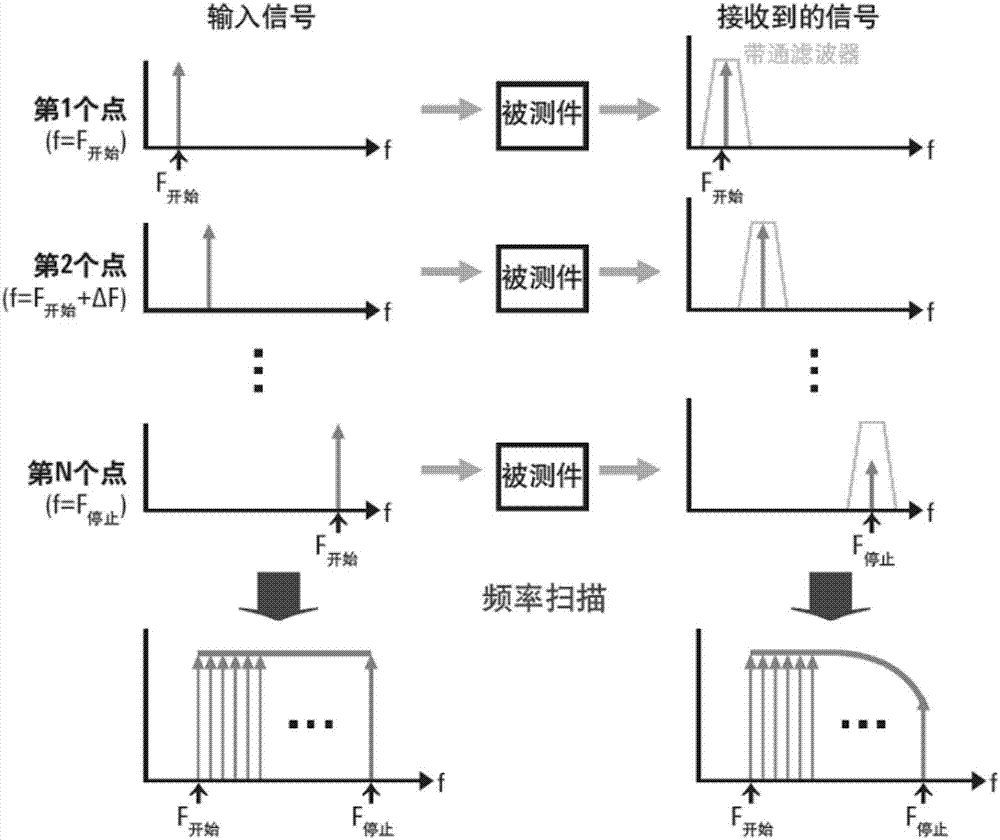
[0093] Conditions: f0=300KHZ, frequency sweep cut-off frequency f_end=19.5GHZ, sweep frequency according to df=3.046828125M as the frequency sweep accuracy, sweep frequency SAO_ALL=6401 frequency points in total, Figure 14 It is a schematic diagram of the amplitude-frequency characteristic of the sweep frequency signal of the present invention, Figure 15 It is a schematic diagram of the phase-frequency characteristic of the frequency sweep frequency signal of the present invention.

[0094] Calculation time measurement range - reciprocal of frequency sweep interval

[0095] T_ns=1 / (detf / 10^9);

[0096] T_ns=328ns,

[0097] Time resolution can also be calculated - the reciprocal of the highest measurement frequency

[0098] DETT_ns=1 / (f_end / 10^9);

[0099] DETT_ns = 0.05ns,

[0100] Therefore, the time accuracy and measurement range of the signal reflection of the entire frequency sweep can be determined as follows

[0101] TT=0:DETT_ns:length(ts_data).*DETT_ns-DETT_ns;...


PUM


Abstract

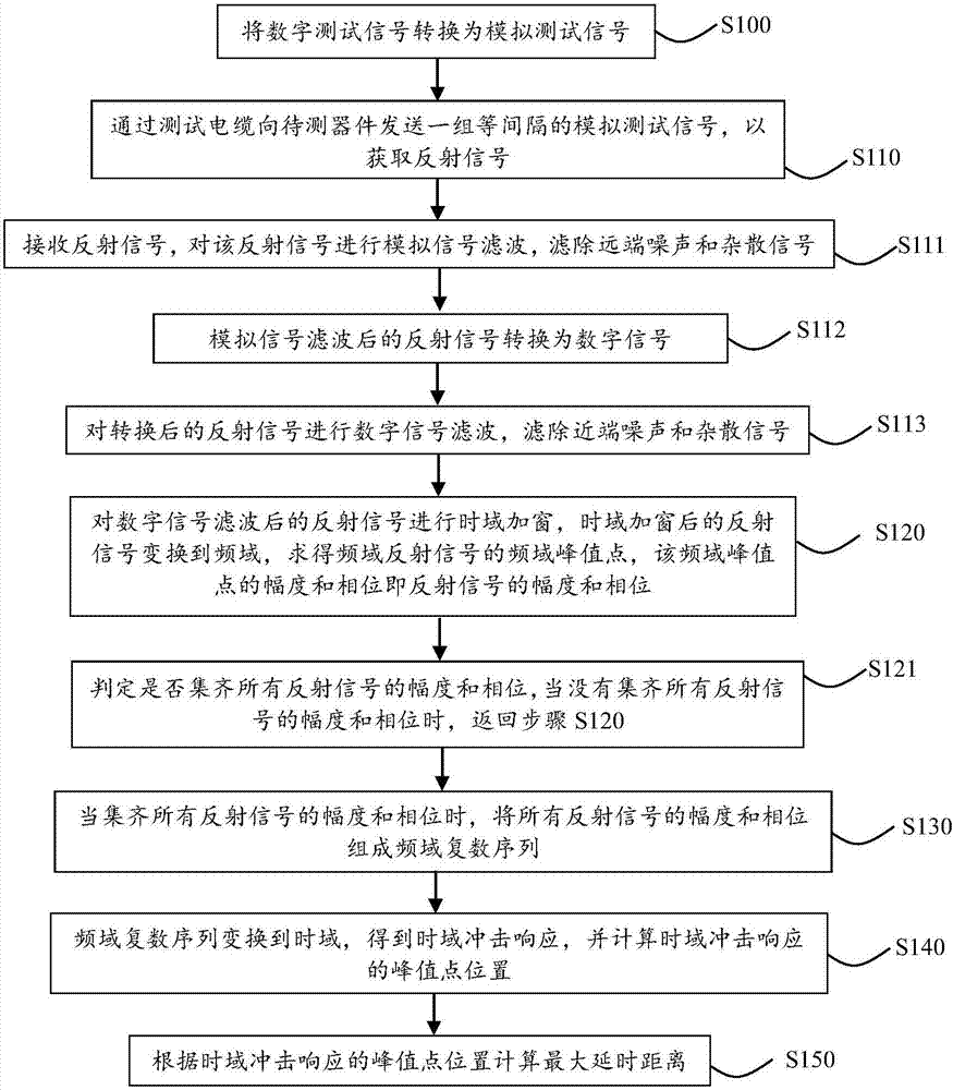
The invention relates to a time domain distance testing method and device. The method comprises steps that a set of equal-interval test signals is sent to a to-be-tested device to acquire reflection signals; the reflection signals are received, and simulation signal filtering of the reflection signals is carried out to filter far-end noise and stray signals; the reflection signals after filteringare converted into digital signals; digital signal filtering of the digital signals is carried out to filter near-end noise and stray signals; time domain windowing of the reflection signals after filtering of the digital signals is carried out; the reflection signals after time domain windowing are transformed to a frequency domain; amplitude and phase of the frequency domain reflection signals are solved; whether the amplitude and the phase of all the reflection signals are acquired is determined, if yes, the amplitude and the phase of all the reflection signals form a frequency domain complex number sequence; the frequency domain complex number sequence is transformed to a time domain to acquire time domain impact response, and the peak point position of the time domain impact responseis calculated; the maximum time delay distance is calculated according to the peak point position of the time domain impact response.

Description

technical field [0001] The invention relates to the field of time-domain reflection measurement, in particular to a time-domain ranging method and device. Background technique [0002] Time Domain Reflectometry (TDR) was introduced in the early 1960s and works on the same principle as radar - sending an impulse signal into a cable under test (or other device or device under test which may not be a good conductor ), when the impulse signal reaches the end of the cable or a fault point on the cable, part or all of the impulse signal will be reflected back to the test instrument. The TDR measurement method is to send an impulse or step excitation signal to the device under test, and then observe the response of the signal in the time domain. During the test, use a step signal generator and a broadband oscilloscope, send the excitation signal with a very fast rising edge speed generated by the step signal generator into the transmission line under test, and then use a broadband...

Claims


Application Information

Patent Timeline
Patent Type & Authority Applications(China)
IPC IPC(8): G01R31/11G01R31/00
Inventor 熊军李梁
Owner BEIJING RINFON TECH CO LTD
Learn More