Oil-water separating device

The technology of an oil-water separation device and a water tank is applied in the field of hydraulic oil separation device, oil-water separation device, and hydrostatic oil, which can solve the problems affecting the cooling of machining tools, waste of resources, waste, etc., so as to avoid sewage treatment costs and improve production. Benefit, effective effect

Pending Publication Date: 2018-01-16
KOCEL MACHINE
View PDF4 Cites 0 Cited by
  • Summary
  • Abstract
  • Description
  • Claims
  • Application Information

AI Technical Summary

Problems solved by technology

[0002] Large vertical lathes, gantry milling machines, boring and milling machines and other large-scale machining equipment are equipped with water tanks. Water or coolant is pumped out of the water tanks through high-pressure water pumps and applied to tool cooling. Equipment using lubricating oil, static pressure oil, and hydraulic oil There are more or less oil leakage situations. The oil leaked from the equipment is washed by the cutting fluid and brought into the water tank together. As a result, the oil in the water tank gradually increases over time, which affects the cooling of machining tools and easily causes the water pump to burn out. etc., affecting the processing efficiency of the equipment
[0003] Usually, the oil in the water tank accumulates too much, and the water in the cooling water tank containing the cutting fluid cannot be used any longer. It can only be pumped out as a whole for centralized discharge, or a special oil-water separator is purchased for oil-water separation. Cause the equipment to shut down. If the oil leakage is serious, too much oil will be accumulated in the water tank for a short time, and the water in the water tank will be replaced as a whole.
In this way, it is time-consuming and labor-intensive, resulting in a waste of resources and at the same time causing a long-term shutdown of the equipment, affecting production
At the same time, the water mixed with cutting fluid in the water tank cannot be reused, resulting in a lot of waste, and the high cost of sewage disposal does not conform to the concept of green manufacturing

Method used


Image

  • Oil-water separating device
  • Oil-water separating device

Examples


Embodiment Construction

[0029] In order to enable those skilled in the art to better understand the technical solutions of the present invention, the present invention will be further described in detail below in conjunction with specific examples. The embodiments described below are exemplary only for explaining the present invention and should not be construed as limiting the present invention. If no specific technique or condition is indicated in the examples, it shall be carried out according to the technique or condition described in the literature in this field or according to the product specification.

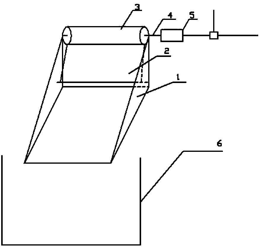
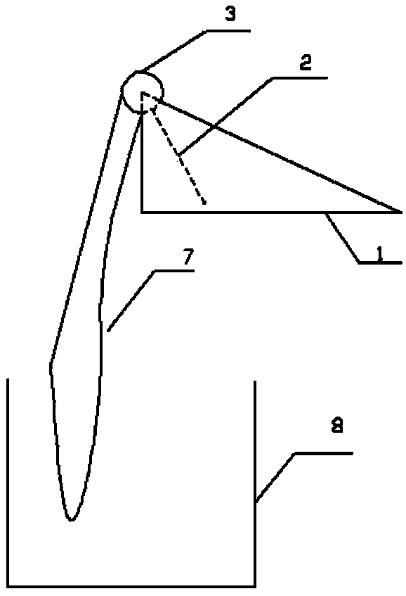
[0030] According to an embodiment of the present invention, the present invention provides an oil-water separation device, figure 1 It is a schematic diagram of a partial structure of an oil-water separation device of the present invention, such as figure 1 As shown, when the oil-water separation device is energized, the motor starts to run, and the motor passes through the coupling to connec...


PUM


Abstract

The invention provides an oil-water separating device, which comprises a main support, an oil scraper, a rotation shaft, a shaft coupler, a motor, an oil barrel, a steel sheet, and a water tank. The adhesion properties of water and oil on a stainless steel sheet are different, so the separating device can separate oil from water and oil on the stainless steel sheet can be removed from the stainless steel sheet by the oil scraper and collected. Moreover, through a time switch, the operation time of the oil-water separating device can be set, and thus an operator does not need to open or close the oil-water separating device by himself. The oil-water separating device is very convenient and is capable of operating under any state of a machine tool without affecting the normal processing. Nocutting fluid is left in the water tank. At the same time, water in the water tank does not need to be changed, and the water resource is saved. The oil-water separating device has the advantages of simple structure, stable operation, and high practicality.

Description

technical field [0001] The invention belongs to the field of large-scale equipment water tanks, in particular to a device for separating static pressure oil and hydraulic oil in a large-scale equipment water tank, in particular to an oil-water separation device for separating oil in a large-scale equipment water tank for collection and treatment. Background technique [0002] Large vertical lathes, gantry milling machines, boring and milling machines and other large-scale machining equipment are equipped with water tanks. Water or coolant is pumped out of the water tanks through high-pressure water pumps and applied to tool cooling. Equipment using lubricating oil, static pressure oil, and hydraulic oil There are more or less oil leakage situations. The oil leaked from the equipment is washed by the cutting fluid and brought into the water tank together. As a result, the oil in the water tank gradually increases over time, which affects the cooling of machining tools and easi...

Claims


Application Information

Patent Timeline
IPC IPC(8): B01D17/022
Inventor 张明红杨保许鹏飞赵彦斌李刚利
Owner KOCEL MACHINE
Why Eureka
Try Eureka