Electrolytic cell for over-oxidation potential water generator

An electrolytic cell and potential water technology, applied in the field of water electrolysis, can solve problems such as low efficiency, low electrolysis efficiency, environmental pollution of cleaning liquid, etc., and achieve the effects of enhanced service life, strong electrolysis capability and low manufacturing cost

Inactive Publication Date: 2018-01-16
烟台美珑机电科技有限公司 +1
View PDF7 Cites 1 Cited by
  • Summary
  • Abstract
  • Description
  • Claims
  • Application Information

AI Technical Summary

Problems solved by technology

[0002] At present, the diaphragm type electrolyzer is one of the main equipment for electrolyzing potential water. An ion diaphragm is installed in the electrolyzer to divide the electrolyzer into two areas. Only one plate can be installed in each area, so the electrolysis efficiency is relatively low. When a large amount of water needs to be electrolyzed per unit time, the electrolysis water output can only be increased by increasing the volume of the electrolytic cell and the area of ​​the electrode plate, but the water output is not directly proportional to the increase in the electrolytic cell solvent and the area of ​​the electrode plate, so low efficiency
[0003] Secondly, in practical application, the above-mentioned diaphragm-type electrolyzer has the problem of calcium accumulation during the electrolysis process, which will hinder the normal operation of the electrode plate and diaphragm, and requires regular cleaning. The cleaning solution may also pollute the environment
[0004] Third, the current electrolytic cells on the market all adopt a rectangular laminated structure, which is simple in processing and assembly.
However, the flow form of the water flow in the rectangular structure is uneven, and the water flow velocity in the area near the water outlet and inlet is greater than that in other areas, which makes the electrolysis process inconsistent, and the electrolysis capacity of the electrolyzer is limited, and the flow rate will not exceed 200L / H. Disinfection and cleaning of some large equipment pipelines

Method used


Image

  • Electrolytic cell for over-oxidation potential water generator
  • Electrolytic cell for over-oxidation potential water generator
  • Electrolytic cell for over-oxidation potential water generator

Examples


Embodiment Construction

[0026] The present invention will be further described below in conjunction with the accompanying drawings, but the present invention is not limited to the following embodiments.

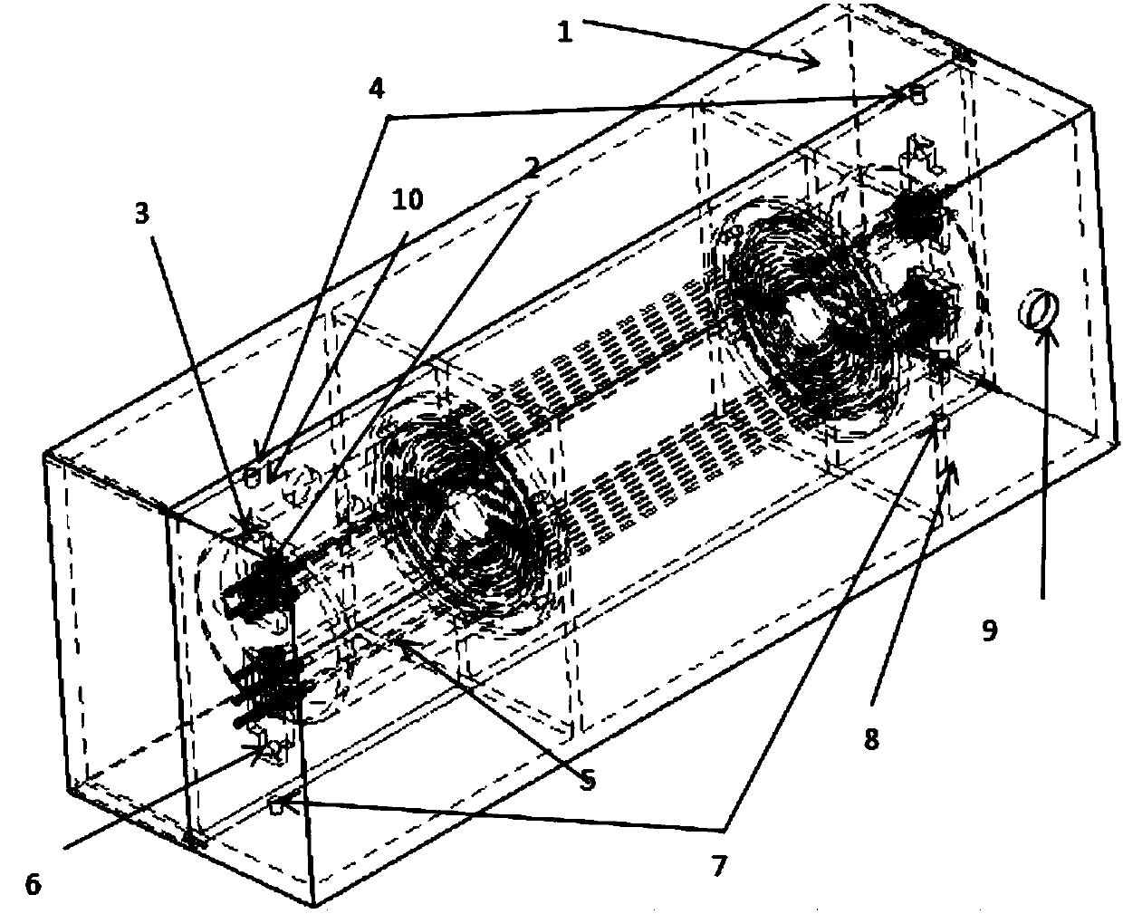
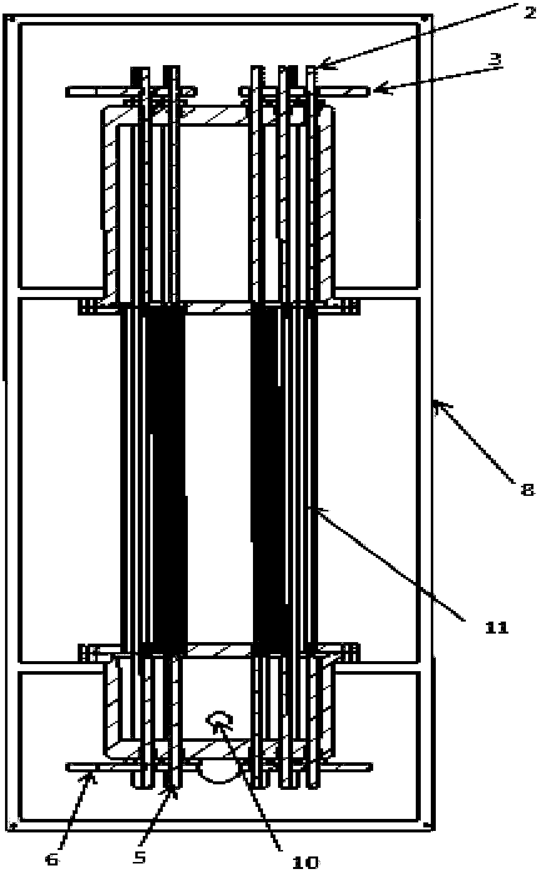
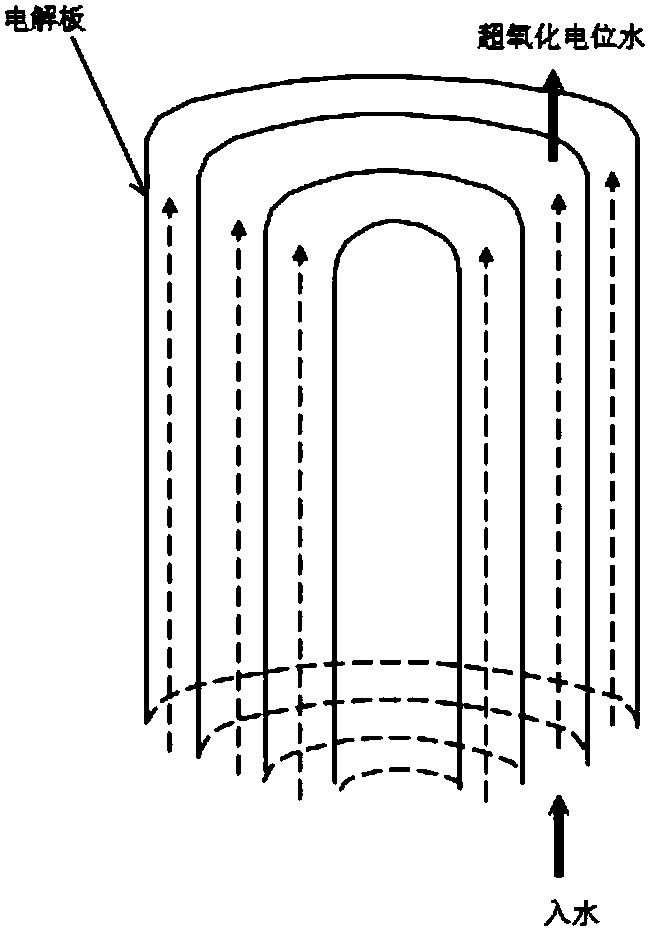
[0027] Such as figure 1 , figure 2 with image 3 As shown, it is a structural schematic diagram of the electrolytic cell used for the super-oxidation potential water generator of the present invention, the electrolytic cell is detachable and separated, and it includes: left housing 1 and right housing 8, left housing 1 and right housing 8 are cuboids; a water inlet 9 is used as the softened tap water inlet; a water outlet 10 is used as the superoxidized potential water outlet generated by electrolysis; four connection ports, of which two anode connection ports 4 and two cathode connections Wiring port 7; alternately arranged circular cathode and anode electrolytic plates (electrode plates 11), the distance between adjacent anode electrode plates and cathode electrode plates is 2-8mm. Wherein the...


PUM

PropertyMeasurementUnit
diameteraaaaaaaaaa

Abstract

The invention discloses an electrolytic cell for an over-oxidation potential water generator. The electrolytic cell comprises an electrolytic cell main body. A plurality of alternately arranged anodeand cathode electrode plates are arranged in the electrolytic cell main body. A gap is formed between the anode and cathode electrode plates. The anode and cathode electrode plates are rounded. Two ends of each one of the anode electrode plates are connected to anode binding posts. Two ends of each one of the cathode electrode plates are connected to cathode binding posts. The anode binding postsand the cathode binding posts are arranged on a binding copper bar. The binding copper bar is connected to an external electrolysis power supply through a port. The electrolytic cell is provided witha water inlet and a water outlet. The electrolytic cell has a simple structure, is easy to assemble, has a strong electrolytic capacity, realizes a low preparation cost, repeatedly utilizes main components, is free of a cleaning agent in the electrolysis process and satisfies environmental protection requirements.

Description

technical field [0001] The invention relates to an electrolytic cell used for a superoxidation potential water generator, belonging to the technical field of water electrolysis. Background technique [0002] At present, the diaphragm type electrolyzer is one of the main equipment for electrolyzing potential water. An ion diaphragm is installed in the electrolyzer to divide the electrolyzer into two areas. Only one plate can be installed in each area, so the electrolysis efficiency is relatively low. When a large amount of water needs to be electrolyzed per unit time, the electrolyzed water output can only be increased by increasing the volume of the electrolytic cell and the area of ​​the electrode plate, but the water output is not directly proportional to the increase in the electrolytic cell solvent and the area of ​​the electrode plate, so low efficiency. [0003] Secondly, in practical application, the above-mentioned diaphragm type electrolyzer produces calcium accumu...

Claims


Application Information

Patent Timeline
Patent Type & Authority Applications(China)
IPC IPC(8): C02F1/461
Inventor 卫志兴宋全厚尹建军林岩侯玉柱吕其江白宝礼
Owner 烟台美珑机电科技有限公司
Why Eureka
Try Eureka