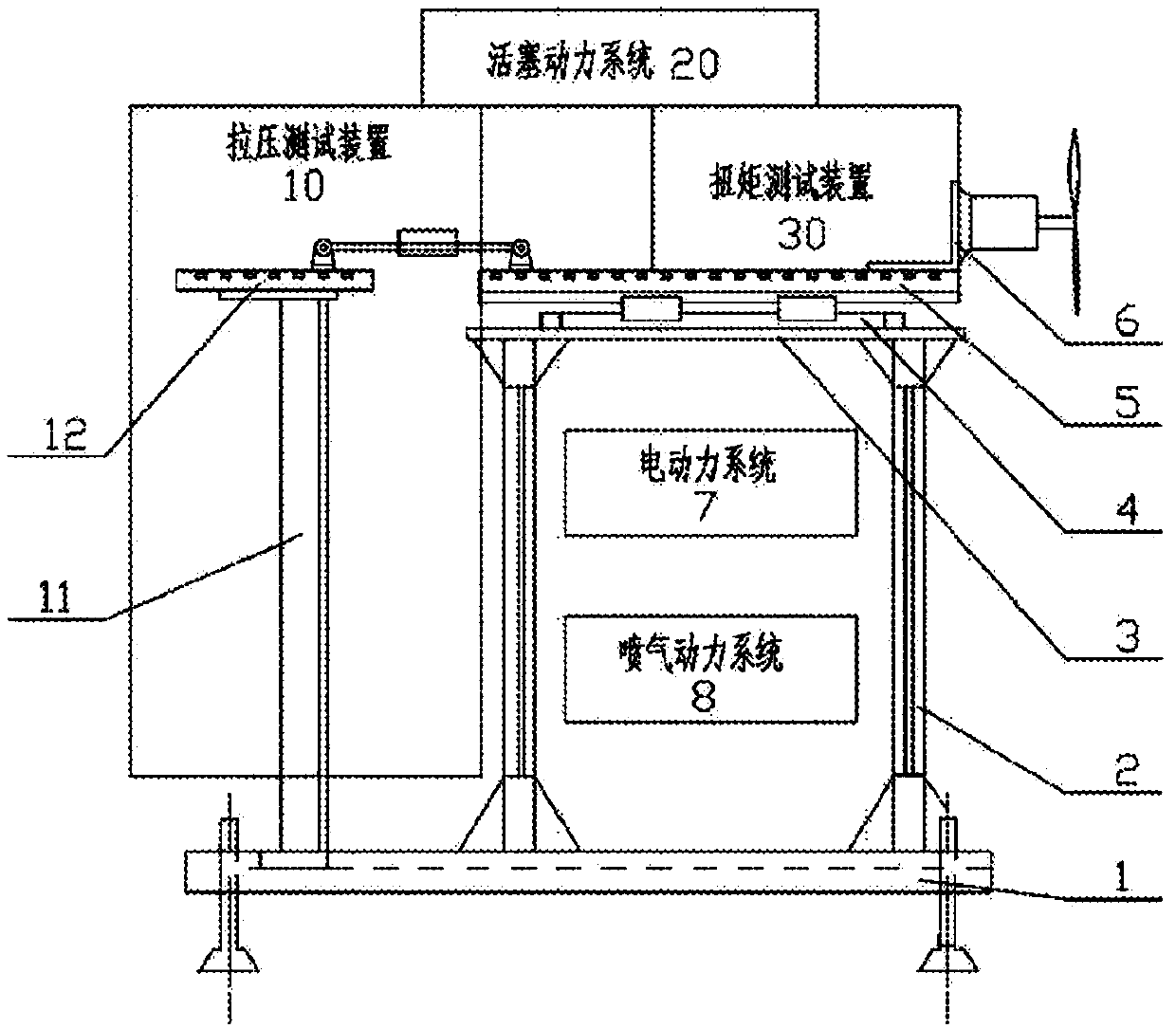
Electric unmanned aerial vehicle power system multifunctional testing stand
A mechanical and multi-functional technology, applied in the field of multi-condition multi-parameter test platforms of power systems, can solve the problems of reduced efficiency, many restrictions on use, backward technology, etc., and achieves reduction in size and weight, convenient installation and maintenance, and simple and compact structure. Effect
- Summary
- Abstract
- Description
- Claims
- Application Information
AI Technical Summary
Problems solved by technology
Method used
Image
Examples
Embodiment 1
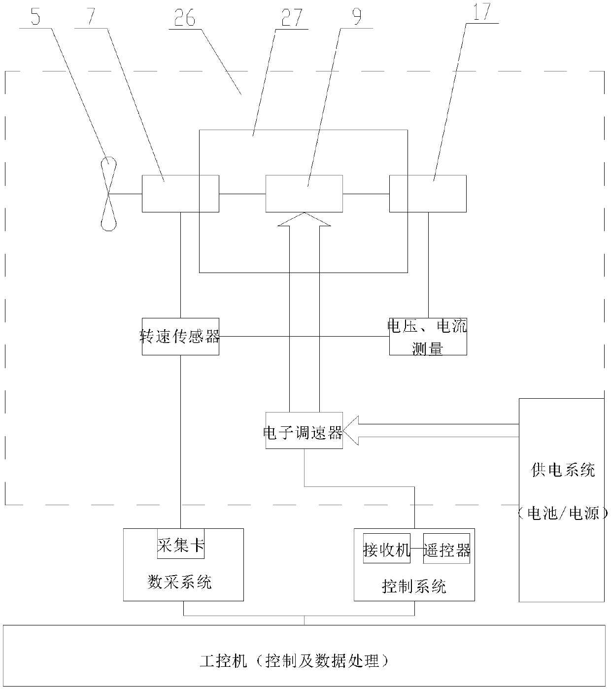
[0068] see figure 2 As shown, the present invention can carry out modular design of different functional areas according to the actual use situation, and the brushless motor 9 of the drone is used as an example for illustration. The modules / components in the above embodiments are independent of each other, and different modules / components can be disassembled and assembled according to different task requirements, and the modules / components are connected through standard interfaces.
[0069] Among them, the test bench assembly 27 in this embodiment is the foundation and support of the entire system, specifically the test bench assembly 27 includes a power mounting frame 13, and the power mounting frame 13 has a front end connecting portion 28 and a rear end connecting portion 29, The brushless motor 9 of the unmanned aerial vehicle is fixedly connected to the front portion of the front end connecting portion 28 of the power mounting frame 13, and a frame base 24, and the power...
Embodiment 2
[0086] Embodiment 2 of the present invention (still taking the brushless motor as an example):
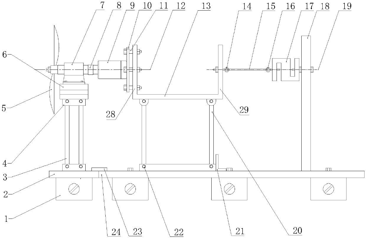
[0087] see Figure 6 As shown, the test stand assembly 27 includes a power mounting frame 13, and the power mounting frame 13 has a front end connection portion 28 and a rear end connection portion 29, and the brushless motor 9 of the drone is fixedly connected to the front end connection portion of the power mounting frame 13. The front portion of part 28, and a frame base 24, power mounting frame 13 is flexibly connected with frame base 24 by power mounting bracket connecting rod 20, and power mounting bracket connecting rod 20 is respectively connected with power mounting frame 13 by connecting rod rotating shaft 22. It is movably connected with the platform base 24, and the power mounting frame 13 has an axial degree of freedom;
[0088] On the platform base 24, a tension sensor installation profile 18 is arranged behind the rear end connecting part of the power installation f...
PUM
 Abstract
Description
Claims
Application Information
 - R&D
- Intellectual Property
- Life Sciences
- Materials
- Tech Scout
- Unparalleled Data Quality
- Higher Quality Content
- 60% Fewer Hallucinations
Browse by: Latest US Patents, China's latest patents, Technical Efficacy Thesaurus, Application Domain, Technology Topic, Popular Technical Reports.
© 2025 PatSnap. All rights reserved.Legal|Privacy policy|Modern Slavery Act Transparency Statement|Sitemap|About US| Contact US: help@patsnap.com


