
Weight method-based ore pulp concentration meter

A densitometer and gravimetric technology, applied in the field of measuring devices for detecting fluid concentration, can solve the problems of easy caking and clogging of measuring equipment, unusable use, affecting the process process, etc., to avoid easy deposition and caking, and prevent clogging. Significant, increased measurement frequency effect

Pending Publication Date: 2018-01-16
ZHEJIANG TIHE INSTR
View PDF0 Cites 4 Cited by
  • Summary
  • Abstract
  • Description
  • Claims
  • Application Information

AI Technical Summary

Problems solved by technology

Due to the high pulp concentration, about 30% to 90%, in the process of pulp concentration measurement, there are disadvantages such as high viscosity, easy adhesion, and easy agglomeration to block the measurement equipment. The online measurement often cannot continue due to the blockage of the pulp concentration measurement equipment. The use will seriously affect the process, so the equipment is also required to have an automatic cleaning function

Method used


Image

  • Weight method-based ore pulp concentration meter
  • Weight method-based ore pulp concentration meter

Examples


Embodiment 1

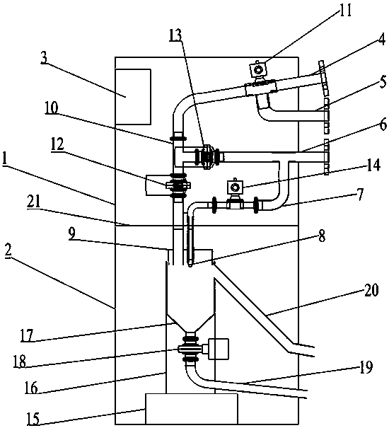
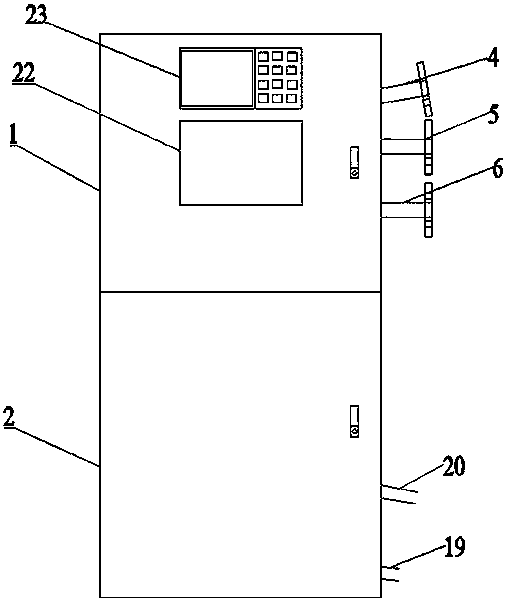
[0027] Such as figure 1 and figure 2 A slurry concentration meter based on the specific gravity method shown includes an upper box body 1, a lower box body 2, a liquid inlet cleaning structure arranged in the upper box body, a circuit control board 3 and a control display screen assembly 23, which are arranged in the lower box body. The weighing and measuring structure in the box body 2, the liquid inlet cleaning structure includes a liquid inlet pipe 4, a circulation pipe 5, a flushing main pipe 6 and a flushing branch pipe 7; the liquid inlet pipe 4 is sequentially provided with an automatic three-way valve 11, The flushing main pipe access section 10, the first electric valve 12, the circulation pipe 5 is connected to the liquid inlet pipe 4 through the automatic three-way valve 11; the flushing main pipe 6 passes through the second electric valve 13 and the flushing on the liquid inlet pipe 4 The connecting section 10 of the main pipe is connected, and the connection bet...

Embodiment 2

[0044] Using the device described in Embodiment 1, the difference is that: the circuit control board described in this embodiment is provided with a remote transmission device, and the corresponding control display system is used simultaneously with the control display screen assembly and the computer.

[0045] The remote transmission device set in the circuit control board can control the operating state and parameter adjustment of the device described in this embodiment through a remote computer, and can display the data obtained by the device described in this embodiment in the measurement on the control display screen assembly Display and upload to the computer for processing, which is convenient for remote monitoring and on-site monitoring at the same time. In addition, using the computer can not only obtain data for analysis and processing, but also automatically adjust the measurement time and frequency of the entire device according to different periods of the process. ...


PUM


Abstract

The invention provides a weight method-based ore pulp concentration meter. The weight method-based ore pulp concentration meter comprises an upper box body, a lower box body, a liquid inlet cleaning structure, a circuit control panel, a control display system and a weighing and measuring structure, wherein the liquid inlet cleaning structure, the circuit control panel and the control display system are arranged in the upper box body; the weighing and measuring structure is arranged in the lower box body; and the liquid inlet cleaning structure, the circuit control panel and the control displaysystem are combined, so that the whole ore pulp concentration meter can realize automatic control, and deposition and scaling phenomena of high-concentration ore pulp in the whole equipment can be avoided. The whole device is reasonable in structural design, extremely small in deviation between the measuring result and manual measuring result, guarantees the use precision and greatly improves themeasuring frequency of the ore pulp concentration.

Description

technical field [0001] The invention relates to a measuring device for detecting fluid concentration, in particular to a gravimetric pulp concentration meter. Background technique [0002] Pulp concentration refers to the content of solid ore particles in the pulp. The pulp concentration has special significance in the operations of grinding, flotation, gravity separation and dehydration. In the grinding process, the grinding fineness and circulation load are mainly adjusted by changing the pulp concentration, and the specified pulp concentration is maintained to ensure a more reasonable grinding particle size characteristic and the highest mill productivity; in the classification operation, the pulp The concentration basically determines the fineness of the graded overflow. The pulp concentration in the flotation process has a double meaning. One is that for different ores, there is a reasonable pulp concentration to obtain the best index at each stage of the sorting pro...

Claims


Application Information

Patent Timeline
Patent Type & Authority Applications(China)
IPC IPC(8): G01N5/00G01N15/06B08B9/032
Inventor 潘勇魏波贾海东郭衷磊金延祥
Owner ZHEJIANG TIHE INSTR
Learn More