Charge measuring circuit

A technology for measuring circuits and charges, which is applied in the field of measuring circuits, can solve problems affecting satellite stability, difficulty in device selection, and inability to take into account high-energy particle measurements, etc., and achieves expanded measurement dynamic range, high measurement accuracy, and low-noise charge-voltage conversion Effect

Active Publication Date: 2018-01-16
INST OF MODERN PHYSICS CHINESE ACADEMY OF SCI
View PDF6 Cites 15 Cited by
  • Summary
  • Abstract
  • Description
  • Claims
  • Application Information

AI Technical Summary

Problems solved by technology

Therefore, it is particularly important to design a charge measurement circuit with high precision and large dynamic range. At present, this type of circuit is also a difficult point in the design of space measurement circuits. Generally, high-energy measurement is realized, but low-energy particle energy measurement cannot be taken into account. On the contrary, If the measurement of low-energy particles is realized, the measurement of high-energy particles cannot be taken into account. In addition, space particles will cause single-event effects on the components in the satellite, which will seriously affect the stability of the satellite’s in-orbit operation. At least 20% is caused by the single event effect, so the selection of the device is also extremely difficult. It is necessary to select the performance index to meet the requirements, but also to choose the one with strong radiation resistance.

Method used


Image

  • Charge measuring circuit
  • Charge measuring circuit
  • Charge measuring circuit

Examples


Embodiment Construction

[0032] In order to make the object, technical solution and advantages of the present invention clearer, the present invention will be further described in detail below in conjunction with specific embodiments and with reference to the accompanying drawings.

[0033] The present invention proposes a feasible solution for the charge measurement circuit, which solves the problem of high precision and large dynamic range charge measurement, improves the system's ability to process signals, and provides a high-precision solution for the detection of particles in the interstellar environment. , The technical solution of large dynamic range charge measurement has great practicability and superiority, and has broad application prospects in many space science and engineering tasks.

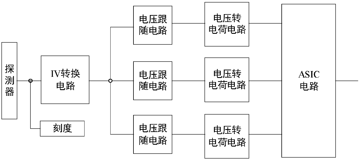
[0034] Specifically, such as figure 1 As shown, the present invention proposes a charge measurement circuit, including an IV conversion circuit, a voltage follower circuit, a voltage-to-charge circuit and ...


PUM


Abstract

The invention relates to a charge measuring circuit, which comprises an IV conversion circuit, a plurality of voltage following circuits, a plurality of voltage-to-charge circuits and an ASIC circuit,and is characterized in that the IV conversion circuit is used for converting detected charge pulse signals into voltage pulse signals; the voltage following circuits are used for performing voltagefollowing on the voltage pulse signals to generate following voltage pulse signals and performing buffer isolation on front and back circuits; the plurality of voltage-to-charge circuits are identicalto the plurality of voltage following circuits in number, arranged at the rear ends of the voltage following circuits in a one-to-one correspondence manner and used for converting the voltage pulse signals outputted by the voltage following circuits into charge pulse signals, and capacitor with different capacitance are connected to the voltage-to-charge circuits respectively so as to expand themeasurement dynamic range; and the ASIC circuit is used for measuring the charge pulse signals outputted by the plurality of voltage-to-charge circuits respectively. The charge measuring circuit has high measurement accuracy, large dynamic range and good linearity.

Description

technical field [0001] The invention relates to a measurement circuit, in particular to a charge measurement technology. Background technique [0002] Since the beginning of the 21st century, scientists all over the world have been accelerating the scientific detection and exploration of the interstellar environment. Because the environment outside the Earth’s atmosphere is filled with a large number of radiation particles of different types and energies, mainly including electrons, protons, alpha particles and heavy particles. Ions, if you want to accurately measure the energy spectrum of these particles, the characteristics of element types and fluxes and their changing laws, you need a high-precision, large dynamic range charge measurement circuit, such as requiring an energy resolution of 10% and a dynamic range of 3.5 ×10³. At present, the interstellar environment parameters are blocked by foreign countries, and all the interstellar environment parameters need to be ob...

Claims


Application Information

Patent Timeline
Patent Type & Authority Applications(China)
IPC IPC(8): G01R29/24
Inventor 杨海波孔洁千奕苏弘赵红赟佘乾顺牛晓阳蒲天磊马晓利
Owner INST OF MODERN PHYSICS CHINESE ACADEMY OF SCI
Why Eureka
Try Eureka