Vertical element riveting system and riveting method thereof

A component and vertical technology, applied in the field of riveting systems, can solve problems such as low work efficiency and low qualified rate of finished products

Active Publication Date: 2018-01-19
邳州厚成自动化设备有限公司
View PDF7 Cites 6 Cited by
  • Summary
  • Abstract
  • Description
  • Claims
  • Application Information

AI Technical Summary

Problems solved by technology

[0003] The riveting of traditional vertical components, wires and resistors is manual, with low work effic

Method used


Image

  • Vertical element riveting system and riveting method thereof
  • Vertical element riveting system and riveting method thereof
  • Vertical element riveting system and riveting method thereof

Examples


Embodiment 1

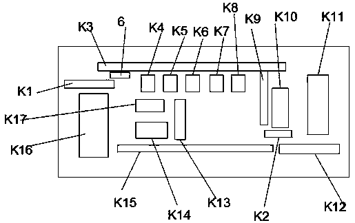
[0069] Embodiment 1. Vertical component riveting system, including: two-leg vertical component vibration feeding mechanism K1, rotating feeding mechanism 6, chain transfer mechanism K3, swing mechanism K4, positive and negative electrode adjustment mechanism K5, leg cutting mechanism K6, Shaping mechanism K7, vertical component quality inspection mechanism K8, vertical component transport mechanism K9, wire automatic clamping mechanism k12, horizontal two-leg component processing mechanism K17, horizontal two-leg component automatic clamping mechanism K13, linkage transport mechanism k15 , Finished product recovery device, positioning clip k2, first copper belt machine K10, second copper belt machine K14, left wire processing mechanism k16, right wire processing mechanism k11; among them: two-legged vertical component vibration feeding mechanism K1 A rotary feeding mechanism 6 is installed on the outer side of the end; a chain transmission mechanism K3 is installed on the outer ...

Embodiment 2

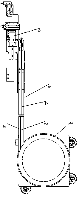
[0070] Embodiment 2. The vertical component riveting system, wherein: the two-leg vertical component vibration feeding mechanism K1 includes a vibration plate 1, a first rectangular slit 2, a vibration plate guide 3, a second rectangular slit 4, and a vibration guide 5 , Rotary feeding mechanism 6; wherein: one side of the vibration plate 1 is fixedly connected to one end of the vibration plate guide 3, and the vibration plate guide 3 is provided with a first rectangular slit 2 that penetrates the upper and lower surfaces of the vibration plate guide 3 , The other end of the vibration plate guide 3 is connected to one end of the vibration guide 5, and the vibration guide 5 is provided with a second rectangular slit 4 that penetrates the upper and lower surfaces of the vibration guide 5; A rotating feeding mechanism is placed on one side; working principle: the lower end surfaces of the vibration plate guide 3 and the vibration guide 5 are respectively installed with vibration mo...

Embodiment 3

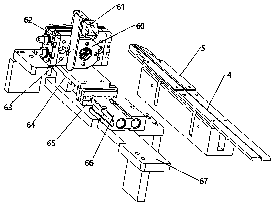
[0071] Embodiment 3, a vertical component riveting system, wherein: the rotating feeding mechanism 6 includes: a rotating disc 60, a mechanical clamp 61, a rotating cylinder 62, a connecting rod 63, a support base 64, a piston rod 65, a cylinder 66, The base 67 is composed of a support base 64 that is slidably mounted on the base 67, and a cylinder 66 is fixedly mounted on the base 67. The cylinder 66 is connected to the support base 64 through a piston rod 65; the support base 64 is fixedly mounted with a rotating Cylinder 62; the right side of the rotating cylinder 62 is connected to the rotating disc 60 through a rotating shaft; a connecting rod 63 is fixedly installed on the arc outer wall of the rotating disc 60; One end is fixedly installed with a mechanical clamp 61; working principle: the rotating cylinder 62 rotates, the mechanical clamp 61 is moved to the vibration guide 5 by the contraction of the cylinder 66, the mechanical clamp 61 clamps the diode, the cylinder 66 ...


PUM


Abstract

The invention relates to a vertical element riveting system and a riveting method thereof. The outer side of the tail end of a two-pin vertical element vibration feeding mechanism K1 is provided witha rotation feeding mechanism 6. The outer side of the rotation feeding mechanism 6 is provided with a chain transmission mechanism K3. The inner side of the chain transmission mechanism K3 is sequentially provided with a swinging flat mechanism K4, a positive and negative electrode adjusting mechanism K5, a pin cutting mechanism K6, a shaping mechanism K7, a vertical element quality detecting mechanism K8 and a vertical element conveying mechanism K9 from left to right. The vertical element conveying mechanism K9 is located between a lower die of a first copper belt machine K10 and the chain transmission mechanism K3. The right side of the first copper belt machine K10 is provided with a right wire processing mechanism k11. The vertical element riveting system and the riveting method thereof have the beneficial effects that the automation rate is high, the production efficiency is high, and operation is easy.

Description

Technical field [0001] The invention relates to a riveting system, in particular to a vertical element riveting system. [0002] The invention also relates to a riveting method of a vertical element riveting system. Background technique [0003] The riveting of traditional vertical components with wires and resistors is manual, with low work efficiency and low pass rate of finished products; the production automation rate is in urgent need of improvement. Summary of the invention [0004] In order to make up for the shortcomings of the prior art, the present invention provides a vertical element riveting system, so as to achieve the purpose of improving production efficiency. [0005] In order to solve the above-mentioned problems, the present invention is implemented through the following technical solutions: [0006] Vertical component riveting system, including: two-leg vertical component vibration feeding mechanism K1, rotating feeding mechanism 6, chain transfer mechanism K3, swi...

Claims


Application Information

Patent Timeline
IPC IPC(8): B21F15/04B21F11/00B21F23/00
Inventor 王惠军黎爱兵邓黎明
Owner 邳州厚成自动化设备有限公司
Why Eureka
Try Eureka