
Capacitor clamping device

A clamping device and capacitor technology, which is applied to hand-held tools, manipulators, program-controlled manipulators, etc., can solve the problems of cumbersome assembly process of capacitors and easy damage to capacitors, and achieve the effects of less manual operation, reasonable structure design and simple operation.

Inactive Publication Date: 2018-01-19
ANHUI JIANGWEI PRECISION IND
View PDF6 Cites 14 Cited by
  • Summary
  • Abstract
  • Description
  • Claims
  • Application Information

AI Technical Summary

Problems solved by technology

[0006] The assembly process of the existing capacitors is relatively cumbersome, and manual handling is easy to damage the capacitors, so we have introduced a capacitor clamping device

Method used


Image

  • Capacitor clamping device
  • Capacitor clamping device
  • Capacitor clamping device

Examples


Embodiment 1

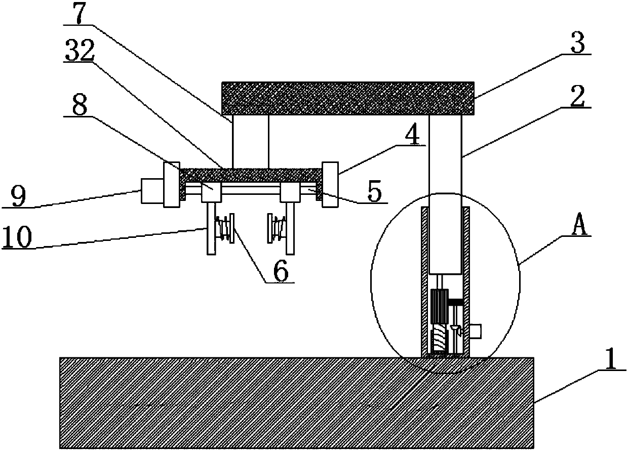
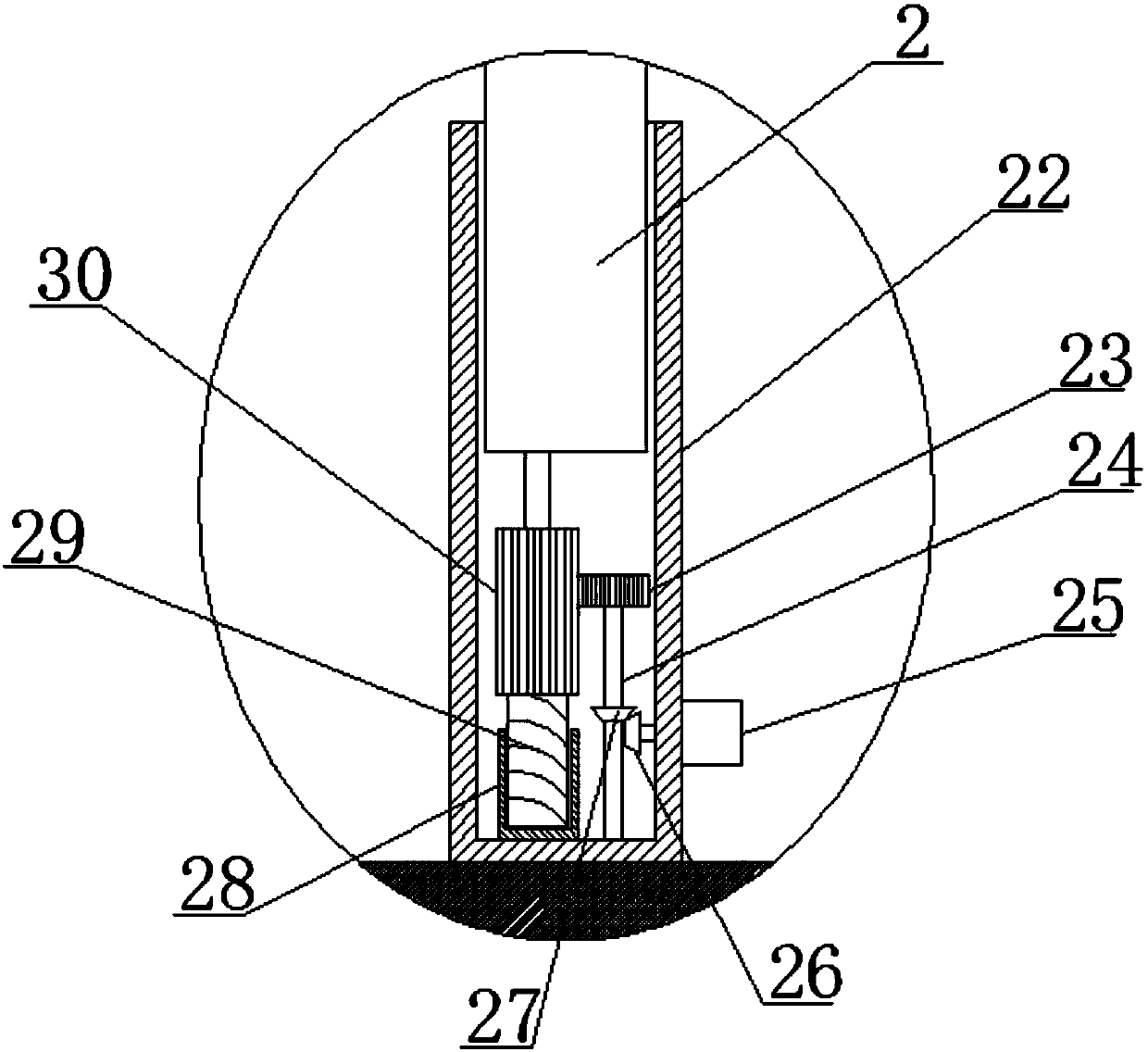
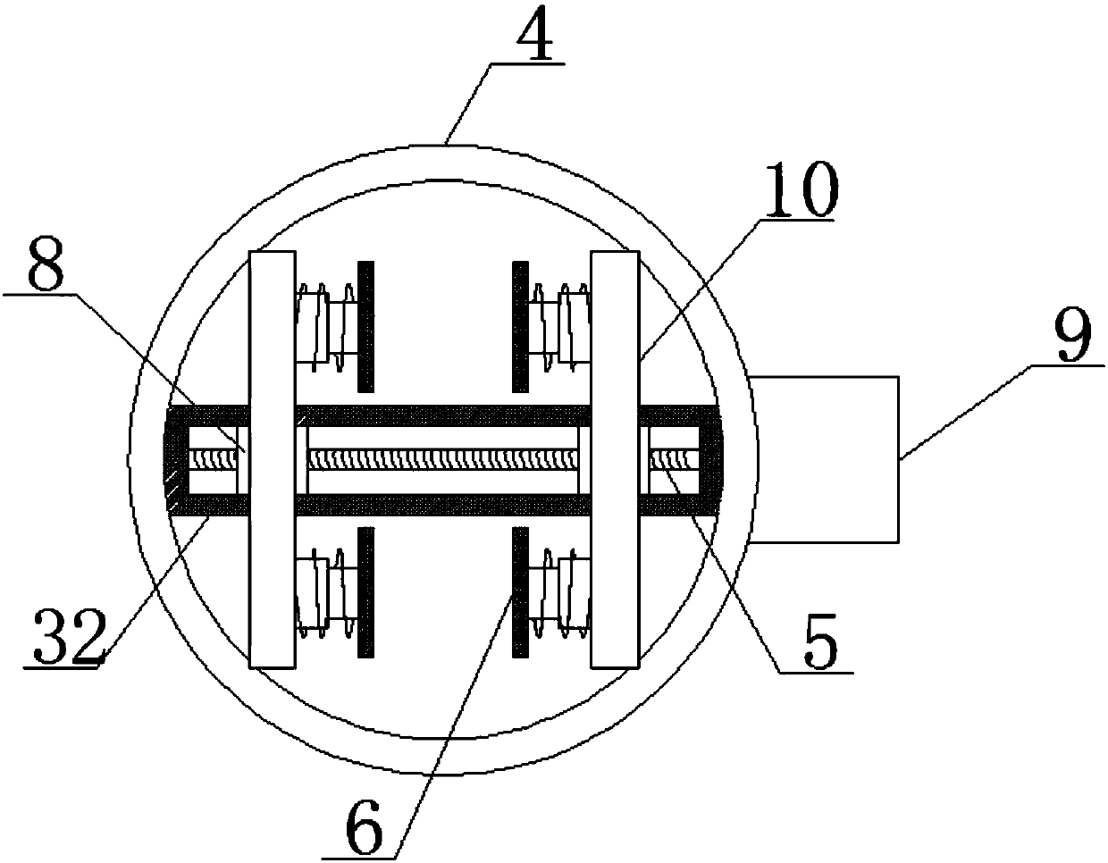
[0023] Embodiment 1: refer to Figure 1-3 , a capacitor clamping device, including a base 1, the upper end of the base 1 is provided with a lifting device, the upper end of the lifting device is fixedly connected with a support rod 3, and the lower end of the support rod 3 is provided with a mechanical arm 7, and the control mechanical arm 7 is controlled by clamping The device clamps the capacitor into the placement groove 31. The lower end of the mechanical arm 7 is provided with a clamping device. The clamping device includes a connecting rod 32 fixedly connected to the lower end of the mechanical arm 7. The outer side of the connecting rod 32 is provided with a fixed ring 4 , the middle part of the connecting rod 32 is provided with a first chute, the side wall of the fixed ring 4 is fixedly connected with the second drive motor 9, and the output shaft of the second drive motor 9 runs through the side wall of the fixed ring 4 and the connecting rod 32 in turn, the second T...

Embodiment 2

[0025] Embodiment 2: refer to Figure 2-6 , the present invention is applied to the assembling and fixing device that is used for capacitor, comprises base 1, and the middle part of base 1 is provided with device cavity, and the inner wall of device cavity is fixedly connected with first drive motor 17, and the inner wall of device cavity is rotatably connected with first Rotating shaft 18, the upper end of the first rotating shaft 18 is fixed with the second rotating disk 19, the output shaft of the first driving motor 17 is welded with the first rotating disk 14, and the upper end of the first rotating disk 14 is fixed with the fan-shaped disk 12, and the axle center of the first rotating disk and The axes of the fan-shaped disks 12 coincide, and the edge of the first rotating disk 14 is provided with a limit rod 13. The distance between the limit rod 13 and the axis of the first rotating disk 14 is slightly greater than the radius of the fan-shaped disk 12, and the edges of ...


PUM


Abstract

The invention discloses a capacitor clamping device. The capacitor clamping device comprises a base. The upper end of the base is provided with a lifting device. The upper end of the lifting device isfixedly connected with a supporting rod. The lower end of the supporting rod is provided with a mechanical arm. The lower end of the mechanical arm is provided with a clamping device body. The clamping device body comprises a connecting rod fixedly connected with the lower end of the mechanical arm. The outer side of the connecting rod is provided with a fixing ring. A first sliding groove is formed in the middle of the connecting rod. The side wall of the fixing ring is fixedly connected with a second driving motor. An output shaft of the second driving motor penetrates through the side walls of the fixing ring and the connecting rod in sequence. The tail end of the output shaft of the second driving motor is fixedly connected with a first threaded rod. The capacitor clamping device is reasonable in structural design, simple in operation and low in needed manual operation, greatly improves the assembly efficiency of a capacitor, and meanwhile reduces damage of the capacitor.

Description

technical field [0001] The invention relates to the technical field of capacitor assembly equipment, in particular to a capacitor clamping device. Background technique [0002] Capacitors, usually referred to as capacitance for their ability to hold charges, are denoted by the letter C. Definition 1: A capacitor, as the name implies, is a 'charged container', a device that holds charges. English name: capacitor. Capacitors are one of the electronic components widely used in electronic equipment, and are widely used in DC blocking, coupling, bypass, filtering, tuning loops, energy conversion, control, etc. in circuits. Definition 2: Capacitor, any two conductors (including wires) that are insulated from each other and are very close to each other form a capacitor. [0003] Capacitance is not the same as capacitor. Capacitance is a basic physical quantity, the symbol C, and the unit is F (farad). [0004] General formula C=Q / U Special formula for parallel plate capacitors...

Claims


Application Information

Patent Timeline
IPC IPC(8): B25B27/00B25J9/10B25J9/12
Inventor 舒均褚诗泉李义纪沿海
Owner ANHUI JIANGWEI PRECISION IND
Features
  • Generate Ideas
  • Intellectual Property
  • Life Sciences
  • Materials
  • Tech Scout
  • Unparalleled Data Quality
  • Higher Quality Content
  • 60% Fewer Hallucinations
Learn More