Intelligent decompression valve system and control method with functions of self-power generation, data acquisition and automatic control

A technology of data acquisition and pressure reducing valve, applied in the direction of functional valve type, engine components, valve details, etc., can solve problems such as maintenance trouble, valve limitation of power generation, turbine shock, etc., to improve utilization rate, alleviate power generation instability, The effect of improving power generation efficiency

Active Publication Date: 2020-02-04
ZHUZHOU SOUTHERN VALVE
View PDF7 Cites 4 Cited by
  • Summary
  • Abstract
  • Description
  • Claims
  • Application Information

AI Technical Summary

Problems solved by technology

However, smart water services are not limited to leakage control, but also need to measure various parameters such as water quality in order to make a comprehensive evaluation of the water flowing in the valve. Therefore, it is necessary to add various types of testing instruments. At this time, simply set the external power supply Or the battery can no longer fully drive all kinds of testing instruments to operate at the same time. If in order to achieve the effect of comprehensive power supply, it is necessary to carry out complex design on the external power supply or battery, which results in a large amount of engineering, high cost and troublesome maintenance in the later stage.
[0003] There are also related cases of hydropower generation in the prior art, but it is only the combination of hydropower generation and valves, and does not involve the detection module, that is, there is no case in the prior art that uses the electric energy of hydropower generation to power the detection module
At the same time, the current water power generation technology in the prior art mainly uses the force of the fluid to directly drive the turbine to rotate. The prior art also uses a spherical runner to drive the electromagnetic induction generator to generate electricity, but the turbine does not specifically target the process of the water flow. The flow is related to the design, that is, when the water flow is large, it will have a large impact on the turbine, which may cause damage to the turbine. At the same time, due to the uneven water flow, the electromagnetic induction generator is unstable when flowing through the turbine, which will directly affect The service life of its rechargeable battery
Moreover, in valve power generation technology, its power generation is often limited by the size of the valve itself

Method used


Image

  • Intelligent decompression valve system and control method with functions of self-power generation, data acquisition and automatic control
  • Intelligent decompression valve system and control method with functions of self-power generation, data acquisition and automatic control
  • Intelligent decompression valve system and control method with functions of self-power generation, data acquisition and automatic control

Examples


Embodiment 1

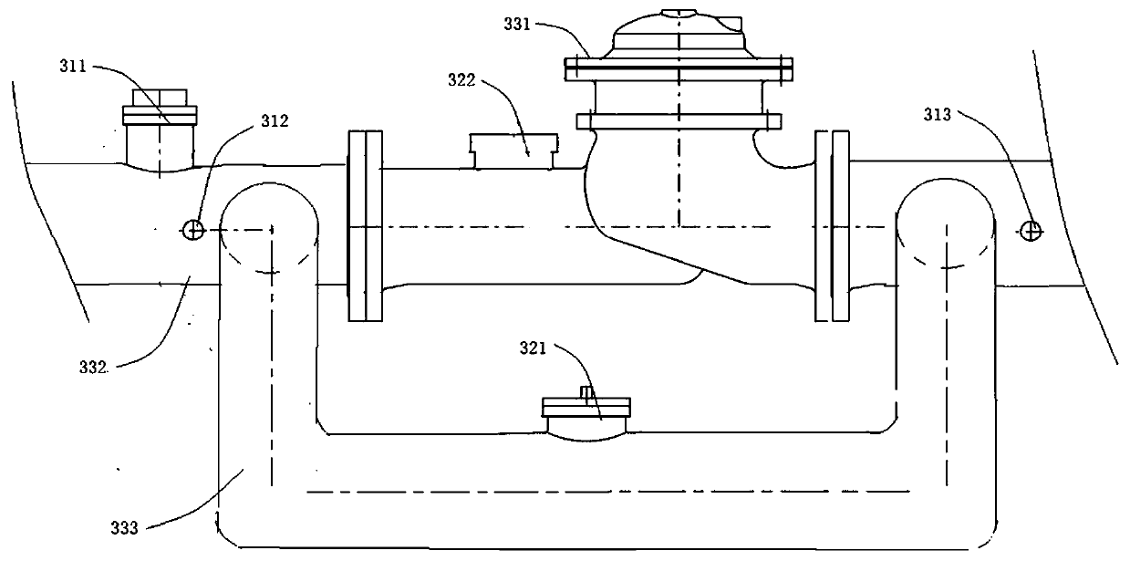
[0047] Such as figure 1 As shown, this embodiment provides an intelligent pressure reducing valve that integrates power generation, data collection, and control functions. This embodiment takes a T-shaped pressure reducing valve as an example. The intelligent decompression valve includes a decompression valve body 33, a power generation device 32, a data acquisition component, a data processing device and a display terminal.

[0048] The power generation device 32 includes a power generation assembly 321 arranged perpendicular to the fluid direction of the pipeline and a battery assembly 322 located outside the valve body; the valve body 331 of the pressure reducing valve is connected to the main pipeline 332, and the valve body is connected in parallel with a bypass pipeline 333, and the power generation The component 321 is disposed inside the bypass pipe.

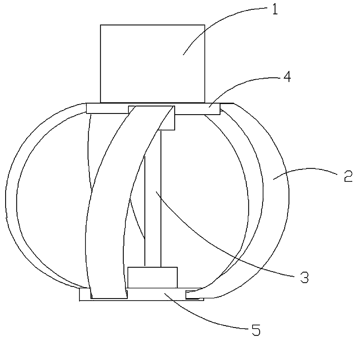
[0049] Such as figure 2 As shown, the power generation assembly 321 includes a generator set 1 and a runner 2; the...

Embodiment 2

[0067] Such as Figure 5 , Image 6 As shown, the difference between this embodiment and Embodiment 1 is that the intelligent decompression valve of this embodiment is a Y-type intelligent decompression valve; the power generation device 32 also includes a swing mechanism; perpendicular to the flow direction. At the inlet of the pressure reducing valve, there is a guide seat 13 for guiding the fluid. The flow passes through the conical guide surface, the cylindrical guide surface and the power generation assembly in sequence, and the diameter of the cylindrical guide surface matches the size of the runner.

[0068] Such as Image 6 As shown, the power generation assembly 9 is placed inside the pipeline, and also includes a swing mechanism that can support the vertical swing of the power generation assembly 9 relative to the axial direction of the fixed shaft 11; the fixed shaft 11 is fixed on a support seat, and in this embodiment The valve housing is fixedly connected; th...

Embodiment 3

[0075] Such as Figure 7 As shown, the difference between this embodiment and Embodiment 1 or Embodiment 2 is that a small runner 8 is provided inside the runner 2; the structure of the small runner 8 is consistent with that of the runner 2; The positions of the two blades of the wheel are staggered. The material of the small runner can be selected from light materials, so as to reduce the weight of the power generation components.

[0076] When the fluid flow rate is constant and the flow rate is normal, the small runner and the big runner rotate under the impact of the fluid, thereby driving the rotating shaft 3 to rotate. Compared with the rotation of the main shaft 3 in Embodiment 1 and Embodiment 2, Embodiment 2 increases The small runner increases the contact surface with the fluid so as to increase the thrust of the fluid on the blades and increase the rotation speed of the main shaft 3 . When the fluid flow rate decreases and the flow velocity decreases, the small ru...


PUM


Abstract

The invention relates to the technical field of valves, and discloses an intelligent pressure reducing valve system with spontaneous power generation, data acquisition and automatic control functionsand a control method. The intelligent pressure reducing valve system comprises a power generating device, data acquisition components, a data processing device and a display terminal, wherein the power generating device comprises a power generating assembly which is arranged to be perpendicular to the flowing direction of a fluid and a battery assembly which is arranged outside a valve body, the valve body is connected to a main pipeline, a bypass pipeline is connected to the valve body in parallel, and the power generating assembly is arranged inside the bypass pipeline; the power generatingassembly comprises a power generating unit and a rotating wheel, the rotating wheel is connected with a rotor of the power generating unit through a rotating shaft, and the rotating wheel comprises blades, an upper base and a lower base; and the data acquisition components are arranged in front of the valve body and / or in the valve body and / or behind the valve body, and corresponding operation isconducted on an actuator through the data processing device according to real-time parameters which are provided by the data acquisition components. The intelligent pressure reducing valve can spontaneously generate power, is stable in power generating performance and has the data acquisition, processing and display functions.

Description

technical field [0001] The invention relates to the field of valves, and more specifically, to an intelligent pressure reducing valve system and control method with functions of self-power generation, data acquisition and automatic control. Background technique [0002] At present, global resources are in short supply, and various energy sources such as water resources and gas sources are in a state of shortage. For water resources, the concept of smart water affairs has emerged as the times require. How to save water and achieve effective leakage control, among which the United States China and Italy have successively proposed some advanced pressure valves with flow detection function, which can control the leakage as small as possible, but the flow detection device needs an external power supply or battery, which depends on the external power supply, and it only needs to control the flow parameters. Detection, low power consumption. However, smart water services are not l...

Claims


Application Information

Patent Timeline
Patent Type & Authority Patents(China)
IPC IPC(8): F16K17/04F16K37/00F16K31/04
Inventor 黄靖谢爱华唐金鹏欧立涛齐浩
Owner ZHUZHOU SOUTHERN VALVE
Why Eureka
Try Eureka