A kind of perovskite film layer has micro-crack perovskite battery and the preparation method of the battery

A perovskite cell, perovskite technology, applied in circuits, photovoltaic power generation, electrical components, etc., can solve problems such as inability to efficiently export excitons

Inactive Publication Date: 2020-03-31
JILIN INST OF CHEM TECH
View PDF2 Cites 0 Cited by
  • Summary
  • Abstract
  • Description
  • Claims
  • Application Information

AI Technical Summary

Problems solved by technology

[0007] The present invention is to solve the problem that the existing perovskite battery cannot efficiently derive the excitons generated when it is excited by photons, and now provides a perovskite film layer with a micro-crack type perovskite battery and the battery method

Method used


Image

  • A kind of perovskite film layer has micro-crack perovskite battery and the preparation method of the battery
  • A kind of perovskite film layer has micro-crack perovskite battery and the preparation method of the battery

Examples


specific Embodiment approach 1

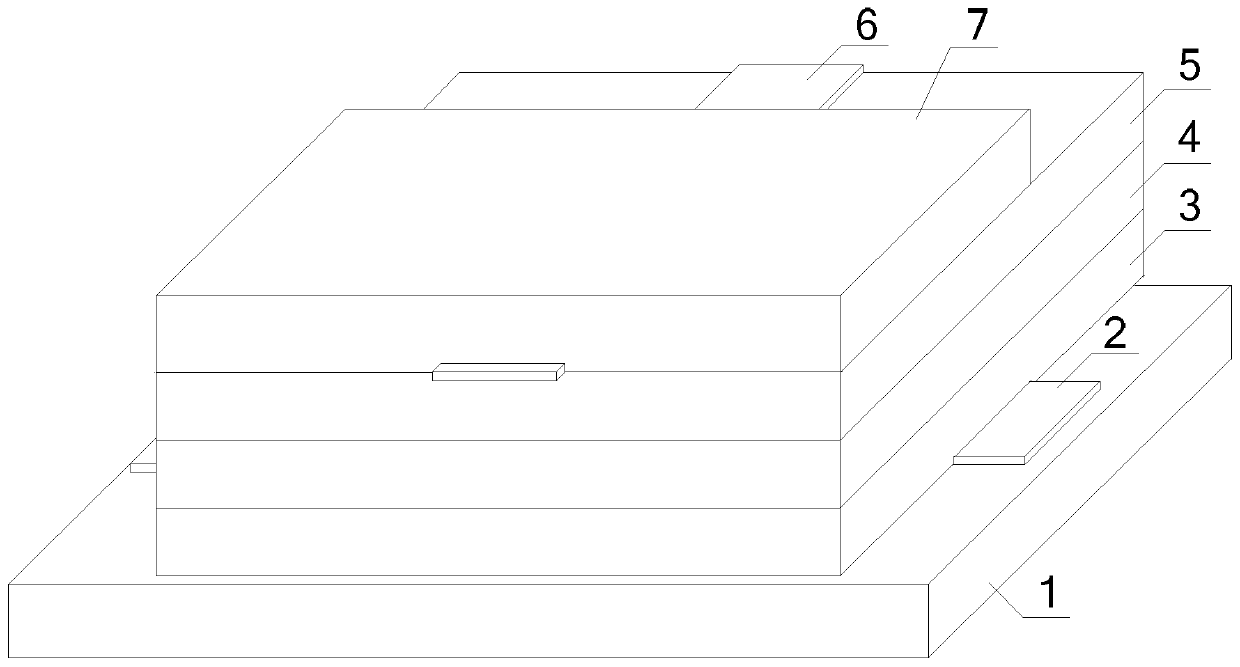
[0018] Specific implementation mode one: refer to figure 1 Describe this embodiment in detail. A perovskite thin film layer described in this embodiment has a perovskite cell with microcracks, including: a first substrate 1, a first electrode 2, a mesoporous layer 3, and a perovskite thin film layer 4, hole transport layer 5, second electrode 6 and second substrate 7;

[0019] The first substrate 1, the first electrode 2, the mesoporous layer 3, the perovskite thin film layer 4, the hole transport layer 5, the second electrode 6 and the second substrate 7 are arranged in order from bottom to top and are in close contact with each other;

[0020] The surface of the perovskite film layer 4 has crack lines.

[0021] A perovskite thin film layer described in this embodiment has a micro-cracked perovskite battery. The innovation of the battery is that the surface of the perovskite thin film layer 4 has crack lines, and these cracks do not penetrate the entire crystal film. This r...

specific Embodiment approach 2

[0022] Specific embodiment 2: This embodiment is a further description of a perovskite thin film layer with a micro-crack type perovskite battery described in specific embodiment 1. In this embodiment,

[0023] Both the first substrate 1 and the second substrate 7 are glass substrates;

[0024] The first electrode 2 is FTO (fluorine-doped SnO 2 transparent conductive glass) electrode, the second electrode 6 is a silver electrode, the thickness is 100nm~200nm;

[0025] The material of the mesoporous layer 3 is TiO 2 , the thickness is 300nm~600nm;

[0026] The material of the perovskite layer 4 is CH 3 NH 3 PB 3 , the thickness is 400nm~1000nm;

[0027] The material of the hole transport layer 5 is Spiro-OMeTAD (2,2',7,7'-tetrakis[N,N-bis(4-methoxyphenyl)amino]-9,9'-spirobifluorene) , with a thickness of 200nm.

specific Embodiment approach 3

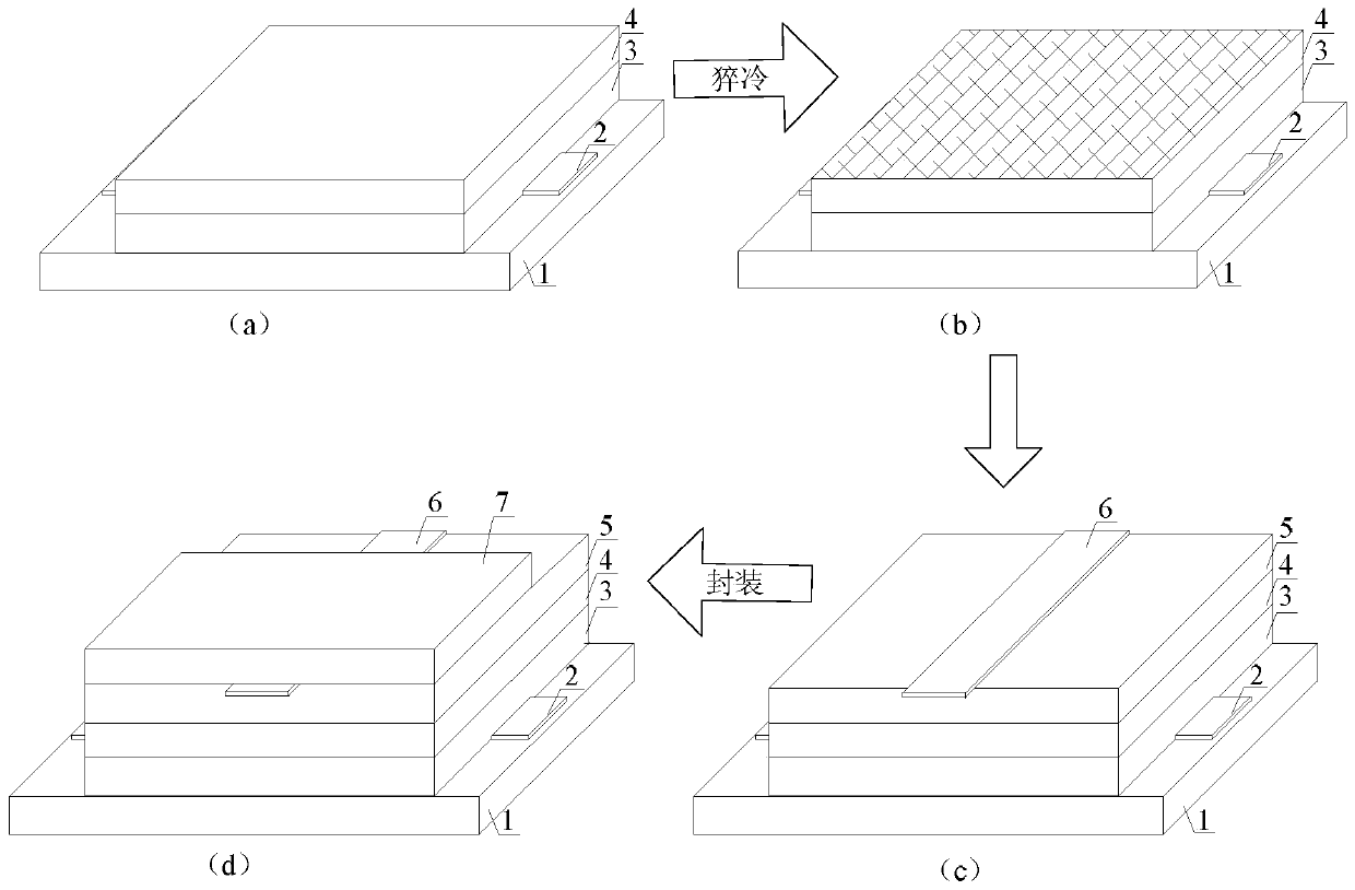
[0028] Specific implementation mode three: refer to figure 2 Specifically illustrate this embodiment, a kind of perovskite film layer described in this embodiment has the method for making the perovskite battery of microcrack type, and this method comprises the following steps:

[0029] Step 1: Spin-coat the mesoporous material on the upper surface of the first substrate 1 covered with the first electrode 2 at a speed of 3000 r / min for 30 seconds to form a mesoporous layer 3;

[0030] Step 2: Spin-coat an alkaline solution of methylamine MAPbI3 perovskite material on the upper surface of the mesoporous layer 3 at a speed of 4500 r / min for 60 seconds to form a perovskite layer 4 and obtain a battery semi-finished product with a perovskite layer 4 on the surface;

[0031] Step 3: thermally annealing the semi-finished battery at 100°C for 10 minutes, and then quenching the semi-finished battery to form cracks on the surface of the perovskite layer 4;

[0032] Step 4: Spin-coat ...


PUM

PropertyMeasurementUnit
thicknessaaaaaaaaaa
thicknessaaaaaaaaaa
thicknessaaaaaaaaaa

Abstract

The invention provides a perovskite cell of which the perovskite thin film layer has micro-cracks and a preparation method of the cell, relates to the technical field of organic solar cells, and aimsat solving the problems that the generated excitons cannot be efficiently exported when the present perovskite cell is under photo excitation. Abundant cracks are formed on the surface of the compactperovskite thin film layer by using the rapid quenching method, and a part of the hole transmission layer is enabled to be infiltrated into the perovskite cracks so that the contact area of the hole transmission layer and the perovskite layer can be increased, and the deep excitons in the perovskite layer are enabled to be more conveniently imported to the hole transmission layer. Besides, the contact surface of the perovskite layer and the hole transmission layer becomes rougher and more disordered so that the incident light is enabled to generate more reflection on the interface, the light path course can be increased and better perovskite material light absorption is facilitated. The preparation method is suitable for preparing the perovskite cell.

Description

technical field [0001] The invention belongs to the technical field of organic solar cells, and relates to a cell with a perovskite film layer having micro-cracks. Background technique [0002] With the rapid development of science and technology, the energy crisis has gradually become prominent. It is predicted that the existing oil and coal resources on the earth will be exhausted within 200 years, so the development and utilization of new energy sources is imminent; at the same time, the burning of petroleum fuels will bring serious damage. Environmental pollution, the discovery of clean new energy will be more meaningful. [0003] At present, the existing clean new energy includes solar power generation, tidal power generation, wind power generation, etc. However, wind power generation, tidal power generation, etc. are subject to many constraints such as geography and space, and cannot meet the needs of today's society in terms of power output. demand. Only solar power...

Claims


Application Information

Patent Timeline
Patent Type & Authority Patents(China)
IPC IPC(8): H01L51/42H01L51/48
CPCY02E10/549Y02P70/50
Inventor 陈丽刘冠辰谢小银
Owner JILIN INST OF CHEM TECH
Why Eureka
Try Eureka