Solar liquid heat temperature difference power generation device

A technology of thermoelectric power generation and solar energy, applied in the field of new solar liquid thermal thermoelectric power generation devices, can solve the problems of not fully utilizing solar energy, not suitable for household use, wasting energy, etc., achieving a good degree of automation, reducing energy loss and extending service life Effect

Inactive Publication Date: 2018-01-19
JIANGSU UNIV
6 Cites 8 Cited by

AI-Extracted Technical Summary

Problems solved by technology

[0003] At present, there have been patent achievements of using solar hot water temperature difference to generate electricity. For example, in a solar thermoelectric power generation water heater CN 20323346 U, it uses the temperature difference between the solar collector and the vacuum heating tube to generate electricity. Small, after reaching the saturation state, the device will stop generating electricity, and the effect of making full use of excess solar energy has not been achieved.
In pat...

Method used

[0034] The bottom of the temperature storage tank 14 communicates with the bottom of the solar water heater 1 through a circulation pipe 19, and a small water pump 20 is provided on the circulation pipe 19 between the temperature storage tank 14 and the solar water heater 1. If there is too much water in the temperature storage tank 14, the ...

Abstract

The invention discloses a solar liquid heat temperature difference power generation device. The solar liquid heat temperature difference power generation device comprises a solar heat accumulation water tank, a hot water pipe, a tap water tank, a cold water pipe, a cold end, a temperature difference power generation element, a hot end, an electromagnetic valve, a cold end water outlet pipe, a hotend water outlet pipe, a constant pressure one-way valve, a temperature storage water tank water inlet pipe, a heat storage water tank, a buoyancy plug and a control circuit, wherein the control circuit comprises a power distribution cabinet, an output electromotive force end of the temperature difference power generation element, a light intensity controller, an electromagnetic valve, a relay anda temperature difference controller which are connected in series in sequence; one end of the storage battery is connected onto a circuit between the power distribution cabinet and the temperature difference controller, and the other end of the storage battery is connected onto a circuit between the output electromotive force end and the light intensity controller. The device is designed by usingtemperature difference power generation and circuit principles, temperature difference formed between the cold end and the hot end enables the temperature difference power generation element to generate electromotive force, generated electrical energy is stored in the storage battery through the power distribution cabinet, and temperature difference power generation is carried out by sufficientlyutilizing solar energy, so that warm water can be generated for providing home application while the liquid cycle energy loss is reduced.

Application Domain

Technology Topic

Image

  • Solar liquid heat temperature difference power generation device
  • Solar liquid heat temperature difference power generation device
  • Solar liquid heat temperature difference power generation device

Examples

  • Experimental program(1)

Example Embodiment

[0029] The present invention will be further described in detail below with reference to the drawings and specific embodiments, but the protection scope of the present invention is not limited to this.
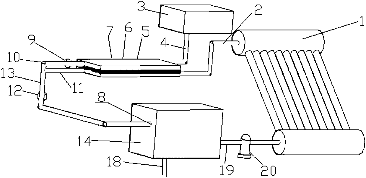
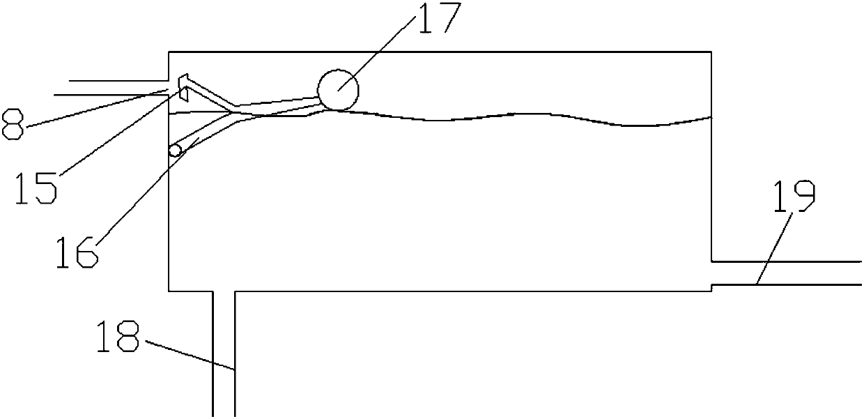
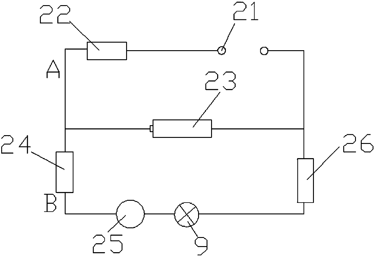
[0030] figure 1 Shown is an embodiment of the solar liquid thermal thermoelectric power generation device of the present invention. The solar liquid thermal thermoelectric power generation device includes a solar hot water storage tank 1, a hot water pipe 2, a tap water tank 3, a cold water pipe 4, and a cold End 5, thermoelectric power generation element 6, hot end 7, solenoid valve 9, cold end outlet pipe 10, hot end outlet pipe 11, constant pressure check valve 12, temperature storage tank inlet pipe 13, temperature storage tank 14, buoyancy plug and Control circuit.
[0031] The tap water tank 3 is arranged at the highest point of the device; the bottom of the tap water tank 3 is connected to the cold end 5 through a cold water pipe 4; the solar hot water storage tank 1 is connected to the hot end 7 through a hot water pipe 2, and the hot water pipe 2 is arranged in the middle part of the side wall of the solar hot water storage tank 1; the thermoelectric power generation element 6 is arranged between the cold end 5 and the hot end 7. When the temperature difference between the hot end 7 and the cold end 5 is formed, the output end of the thermoelectric power generation element 6 generates Electromotive force.
[0032] One end of the hot end water outlet pipe 11 is in communication with the hot end 7, and one end of the cold end water outlet pipe 10 is in communication with the cold end 5; the solenoid valve 9 is arranged in the cold end water outlet pipe 10; the cold end water outlet pipe 10 is connected to the hot end The other end of the outlet pipe 11 is connected to one end of the inlet pipe 13 of the temperature storage tank. The constant pressure check valve 12 is arranged in the inlet pipe 13 of the temperature storage tank. When the solenoid valve 9 is opened, the water pressure becomes larger. The one-way valve 12 is opened; the other end of the inlet pipe 13 of the temperature storage tank communicates with the top of the temperature storage tank 14. A buoyancy plug is provided in the temperature storage tank 14, and the buoyancy plug is located at the inlet of the inlet pipe 13 of the temperature storage tank 8 locations.
[0033] Such as figure 2 As shown, the buoyancy plug includes a buoyancy rod 16, a buoyancy ball 17, and a plug 15. The buoyancy rod 16 is connected to the side wall rotation pair of the temperature storage tank 14, and one end of the buoyancy rod 16 is provided with a buoyancy ball 17, and the other end of the buoyancy rod 16 Set the stopper 15.
[0034] The bottom of the temperature storage tank 14 is communicated with the bottom of the solar water heater 1 through a circulation pipe 19, and a small water pump 20 is provided on the circulation pipe 19 between the temperature storage tank 14 and the solar water heater 1. If there is too much water in the warm water tank 14, the small water pump 20 can be manually turned on to fill the solar water heater 1 with water. The purpose is to reheat the excess warm water and save energy.
[0035] A water pipe 18 is also provided at the bottom of the warm water tank 14, and the hot water in the warm water tank 14 can be supplied to the household through the water pipe 18.
[0036] The outer layers of the hot water pipe 2, the hot end water outlet pipe 11, the warm water tank inlet pipe 13 and the warm water tank 14 are all provided with thermal insulation materials to reduce energy loss and provide warm water.
[0037] The hot water pipe 2 and the cold water pipe 4 are both slender and have vertical pipe sections, so that the hot end and the hot water storage tank are reduced during power generation, and the cold end exchanges heat with the cold water in the tap water tank.
[0038] Such as image 3 As shown, the control circuit includes a power distribution cabinet 22, an output electromotive force terminal 21 of a thermoelectric power generation element 6, a light intensity controller 26, a solenoid valve 9, a relay 25, and a thermostat 24 connected in series. One end of the 12V battery 23 is connected On the circuit between the power distribution cabinet 22 and the temperature difference controller 24, the other end is connected to the circuit between the output electromotive force terminal 21 and the light intensity controller 26. The power distribution cabinet 22, the output electromotive force terminal 21 of the thermoelectric power generation element 6 and the battery 23 communicate to form a branch A; the light intensity controller 26, the solenoid valve 9, the relay 25, the thermostat 24 and the storage battery 23 communicate to form a branch B.
[0039] The thermoelectric power generation module includes a solar hot water storage tank 1, a tap water tank 3, a cold water pipe 4, a hot water pipe 2, a hot end 7, a thermoelectric power generation element 6, and a cold end 5. The power module includes a battery 23 and a power distribution cabinet 22. The power distribution cabinet 22 can stabilize current and voltage, reduce energy loss, and protect and extend the service life of the battery 23. The valve and its control circuit module include a light intensity controller 26, a temperature difference controller 24, and a solenoid valve 9, which can realize the automatic operation of the device.
[0040] The working principle of the present invention is:
[0041] The hot water at the hot end 7 is supplied by the solar hot water storage tank 1, and the cold water at the cold end 5 is supplied by the tap water tank 3. A temperature difference is formed at both ends, so that the thermoelectric power generation element 6 generates a potential difference, and the branch A is connected to generate electricity. When the temperature difference between the hot end 7 and the cold end 5 becomes smaller and the external light intensity reaches the set value, the light intensity controller 26, the temperature difference controller 24 and the branch B will be connected to open the solenoid valve 9; due to the tap water tank 3 At this time, the water pressure at the constant pressure check valve 12 becomes larger, and the constant pressure check valve 12 opens. The water in the cold end 5 and the hot end 7 flows into the temperature storage tank 14 due to gravity. When new hot water and cold water are refilled at both ends, the higher temperature difference disconnects the temperature difference controller 24 from the circuit, and the solenoid valve 9 is closed again to start a new round of power generation. The warm water accumulated in the warm water tank 14 can be used for daily household use through the water pipe 18, and when it is sufficient, it can be recirculated to solar energy for heating by the small electric pump 20, because the bottom of the warm water tank 14 and the solar hot water storage tank 1 The height difference is small, and therefore, the electric energy consumed by the small water pump 20 is also small. Since the hot water pipe 2 is located in the middle of the solar hot water storage tank 1, sufficient hot water is left in the solar energy for use. When the temperature difference controller 24 is closed, the output electromotive force terminal 21 of the thermoelectric power generation element 6 has no electromotive force and the branch A is open, so there are only two states of charging and outputting for the battery 23. A buoyancy rod 16 is provided in the temperature storage tank 14. When the water level of the temperature storage tank 14 rises to a certain level, the buoyancy ball 17 is stressed. Due to the principle of leverage, the plug 15 will block the water inlet 8 of the inlet pipe 13 of the temperature storage tank, and the device Stop operation. When using water, the user can use cold water, warm water in the temperature storage tank 14 and solar hot water to reasonably match the suitable water temperature.
[0042] In the present invention, the temperature difference controller 24 and the light intensity controller 26 cooperate to control the valve, so that the device can work normally when the external light intensity is sufficient. The valve opens when the temperature difference between the cold end 5 and the hot end 7 becomes smaller. The valve closes when the temperature difference at terminal 7 increases. The temperature difference formed between the cold end 5 and the hot end 7 causes the thermoelectric power generation element to generate electromotive force, and the generated electric energy is stored in the battery 23 through the power distribution cabinet 22. The invention makes full use of solar energy for thermoelectric power generation, reduces the energy loss of liquid circulation, and can produce warm water at the same time to provide household use. The invention is suitable for rural areas and other areas, especially southern areas and other areas, with a wide range of applications.
[0043] It should be understood that although this specification is described in accordance with various embodiments, not each embodiment only contains an independent technical solution. This narration in the specification is only for clarity, and those skilled in the art should regard the specification as a whole The technical solutions in the embodiments can also be appropriately combined to form other implementations that can be understood by those skilled in the art.
[0044] The series of detailed descriptions listed above are only specific descriptions of the feasible embodiments of the present invention. They are not used to limit the scope of protection of the present invention, and any equivalent embodiments or embodiments made without departing from the technical spirit of the present invention All changes shall be included in the protection scope of the present invention.

PUM

no PUM

Description & Claims & Application Information

We can also present the details of the Description, Claims and Application information to help users get a comprehensive understanding of the technical details of the patent, such as background art, summary of invention, brief description of drawings, description of embodiments, and other original content. On the other hand, users can also determine the specific scope of protection of the technology through the list of claims; as well as understand the changes in the life cycle of the technology with the presentation of the patent timeline. Login to view more.

Similar technology patents

Integrated electro-hydraulic servo driver hydraulic system

Owner:THE GENERAL DESIGNING INST OF HUBEI SPACE TECH ACAD

Classification and recommendation of technical efficacy words

  • Reduce energy loss
  • Protection life

High-precision maximum power point tracing method

ActiveCN101651436AOvercoming misjudgmentReduce energy lossPV power plantsPhotovoltaic energy generationObservation methodMppt algorithm
Owner:SUNGROW POWER SUPPLY CO LTD

Lube Base Oil, Process for Production Thereof, and Lubricating Oil Composition

ActiveUS20100041572A1High level of functionReduce energy lossTin organic compoundsGroup 5/15 element organic compoundsIodine valueEnergy loss
Owner:NIPPON OIL CORP +1
Why Eureka
Try Eureka