Assembly block
A technology of assembling blocks and stepped holes, which is applied in the direction of photovoltaic modules, supporting structures of photovoltaic modules, sustainable buildings, etc., can solve the problems that it is difficult to use to build foundations with a horizontal top surface, and achieve shortened construction period, high construction accuracy, Reduce the effect of formwork assembly
- Summary
- Abstract
- Description
- Claims
- Application Information
AI Technical Summary
Problems solved by technology
Method used
Image
Examples
no. 1 example
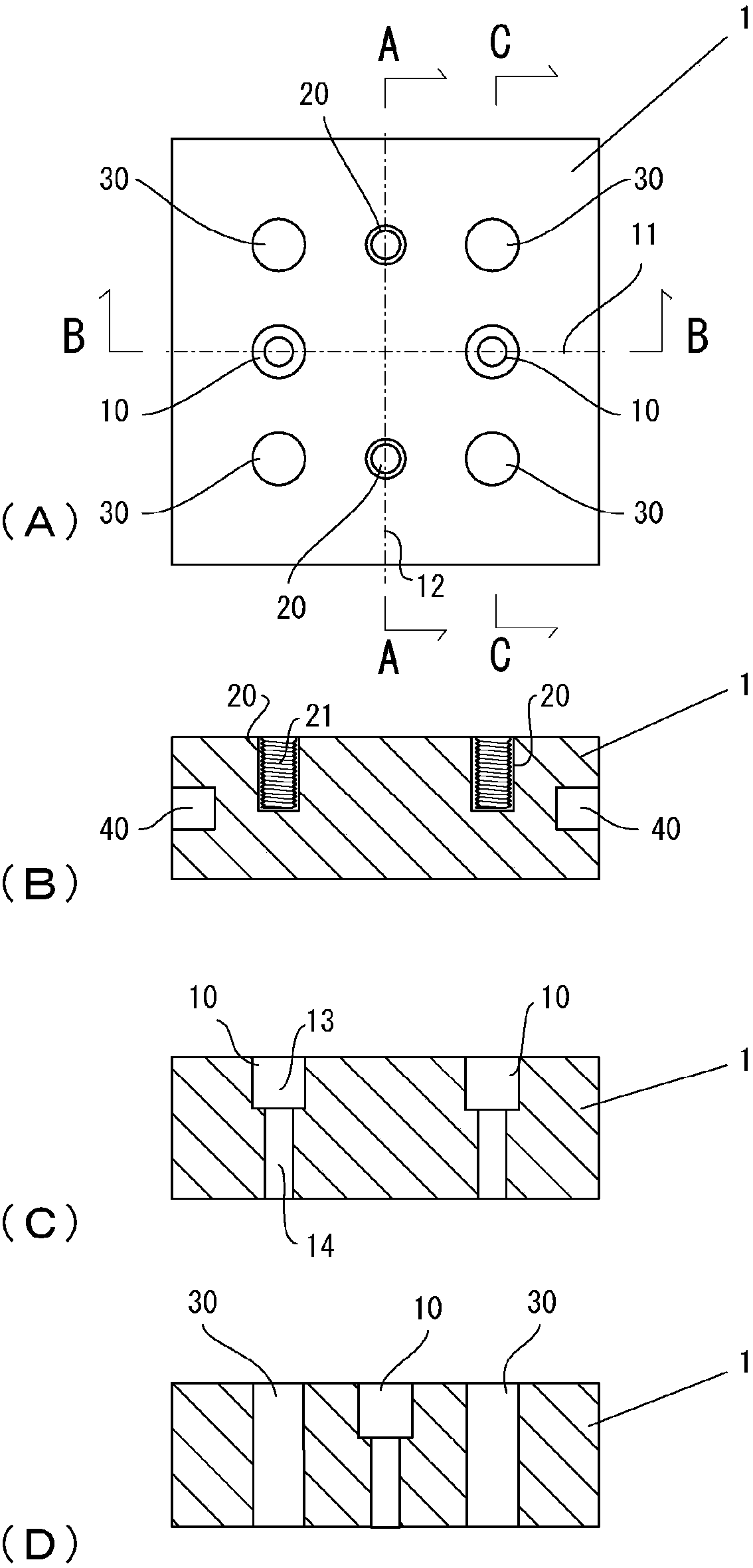
[0068] In the first embodiment, an assembly block whose planar shape is a square flat plate will be described. refer to figure 1 The assembly block of the first embodiment will be described. figure 1 Figure (A) in (A) shows the top view of assembly block 1, figure 1 Figure (B) in the figure 1 A-A position sectional view of (A) figure, figure 1 Figure (C) in the figure shows figure 1 B-B position sectional view of (A) figure, figure 1 Figure (D) in the figure 1 Sectional view of position C-C in (A) panel.
[0069] The assembly block 1 of the first embodiment is in the shape of a square with a side length of 30 cm and a thickness of 10 cm. The assembly block 1 is provided with a pair of stepped holes 10 through which bolts are passed and fixed, and a pair of inserts 20 serving as recessed portions. A first imaginary line 11 connecting a pair of stepped holes 10 and a second imaginary line 12 connecting a pair of inserts 20 intersect on the central axis of the flat ...
no. 2 example
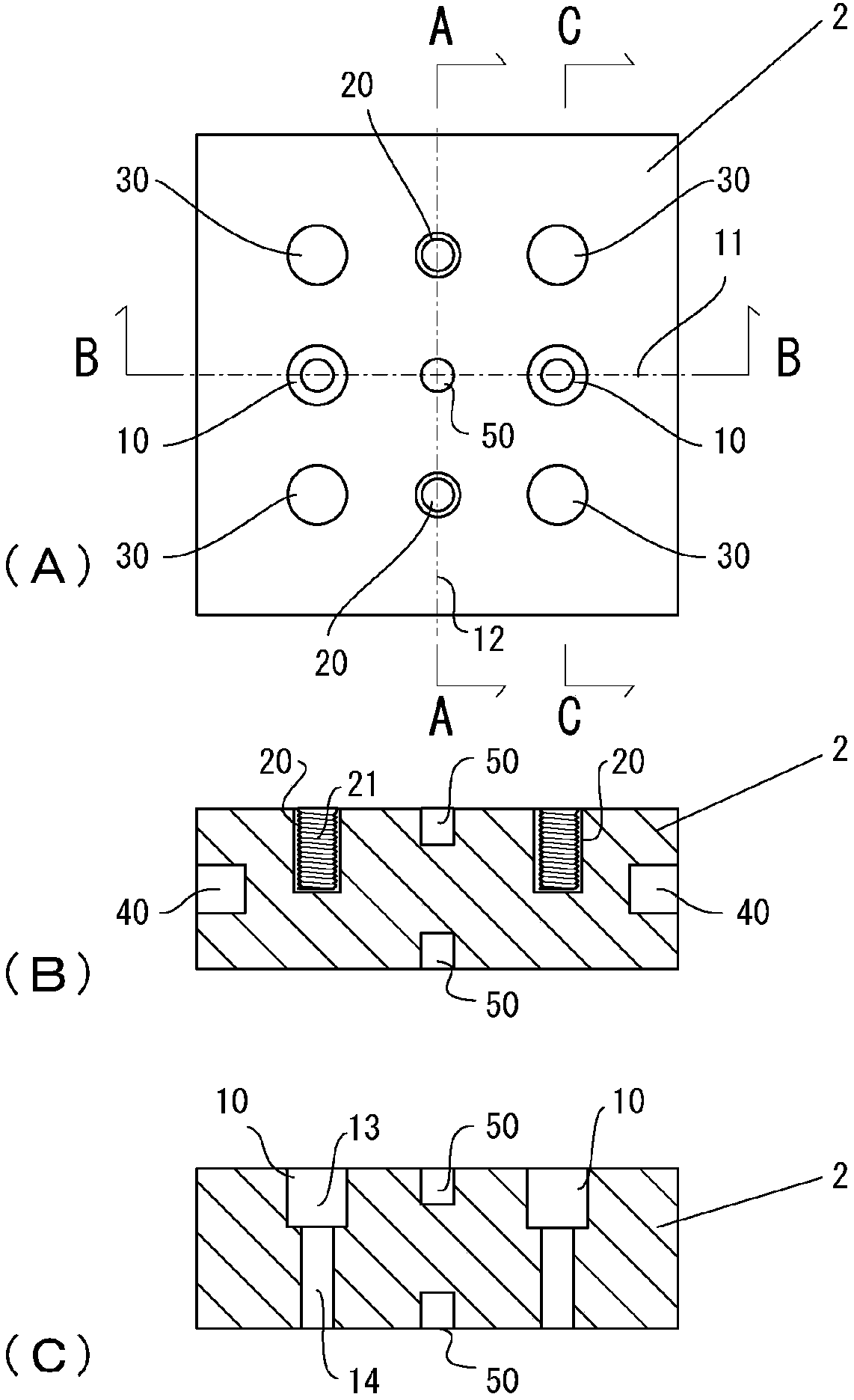
[0073] In the second embodiment, refer to figure 2 An assembly block in which the concave portion 50 as an intersection point alignment means is formed at the position of the intersection point between the top surface and the bottom surface of the assembly block 1 of the first embodiment will be described. figure 2 Figure (A) in (A) shows the top view of assembly block 2, figure 2 Figure (B) in the figure 2 A-A position sectional view of (A) figure, figure 2 Figure (C) in the figure shows figure 2 B-B position sectional view of (A) figure. figure 2 The cross-section of the C-C position of the (A) figure and figure 1 Figure (D) in (D) is the same, so it is omitted.
[0074] Except for the recess 50, the assembly block has the same structure as that of the first embodiment. Parts with the same configuration are given the same reference numerals and their descriptions are omitted. The concave portion 50 is formed so that the cylindrical shape is removed at the posi...
no. 3 example
[0087] In the third embodiment, it is explained that the roof 110 of a building in which air-conditioning equipment is installed on the roof is installed so that a plurality of solar power generation panels 112 can be installed on parts other than the installed equipment 111 to enable efficient use of the roof. An example of multiple foundation 90's. refer to Figure 5 , Figure 6 A state in which a plurality of foundations 90 are installed on a roof 110 on which a drainage slope is formed will be described. Figure 5 shows a configuration diagram of the machine 111, solar panels 112 and foundation 90 on the roof, Figure 6 A cross-sectional view illustrating a foundation 90 disposed on a roof is shown.
[0088] Below, refer to Figure 5 The configuration of the base 90 will be specifically described. Since the size of the unit 113 of the solar power generation panel 112 is limited, on the roof 110, for the solar power generation panel on the left column in the figure, th...
PUM
 Abstract
Description
Claims
Application Information
 - R&D
- Intellectual Property
- Life Sciences
- Materials
- Tech Scout
- Unparalleled Data Quality
- Higher Quality Content
- 60% Fewer Hallucinations
Browse by: Latest US Patents, China's latest patents, Technical Efficacy Thesaurus, Application Domain, Technology Topic, Popular Technical Reports.
© 2025 PatSnap. All rights reserved.Legal|Privacy policy|Modern Slavery Act Transparency Statement|Sitemap|About US| Contact US: help@patsnap.com


