
Motor with cooling duct

A technology for cooling pipes and pipes, applied in the direction of electric components, electrical components, electromechanical devices, etc., can solve the problems of unfavorable lightweight design, single cooling pipe, increase the weight of the motor, etc. perturbation effect

Active Publication Date: 2018-01-23
CSR ZHUZHOU ELECTRIC LOCOMOTIVE RES INST
View PDF3 Cites 11 Cited by
  • Summary
  • Abstract
  • Description
  • Claims
  • Application Information

AI Technical Summary

Problems solved by technology

However, the existing cooling pipes are relatively single. In order to improve the heat dissipation capacity of the cooling system, the heat dissipation area is generally only increased by changing the number of cooling pipes, but this will increase the weight of the motor, which is not conducive to lightweight design
[0005] In view of this, in order to solve the relatively single defect of the current cooling pipeline, the inventor of the present invention designed a motor with a special cooling pipeline that can effectively improve the heat dissipation capacity on the basis of ensuring a lightweight design

Method used


Image

  • Motor with cooling duct
  • Motor with cooling duct
  • Motor with cooling duct

Examples


Embodiment Construction

[0038] The present invention will be further described below in conjunction with the drawings.

[0039] The design principle of the present invention is based on the Newtonian cooling formula:

[0040] Φ=hAΔT

[0041] In the formula, Φ——loss generated by the motor, the unit is W;

[0042] h——Convection heat transfer surface heat transfer coefficient, the unit is W / m 2 ·K;

[0043] A——The heat exchange area, the unit is m 2 ;

[0044] ΔT——The average temperature difference on the heat exchange surface.

[0045] For the motor, the internal heat flow Φ remains unchanged. To reduce the temperature difference, that is, to reduce the temperature rise of the motor, it is necessary to increase the convective heat transfer coefficient h on the heat exchange surface or increase the heat dissipation area A. The increase of the heat dissipation area will increase the weight of the motor, which is not conducive to the lightweight design and power density of the motor. Therefore, the heat dissipation ...


PUM


Abstract

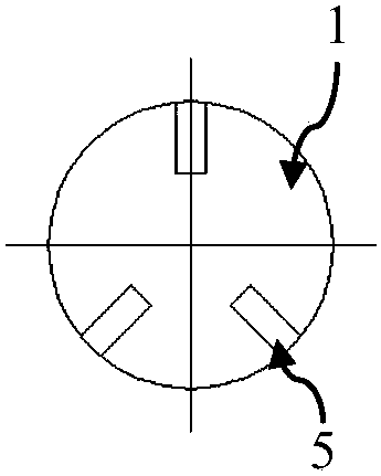
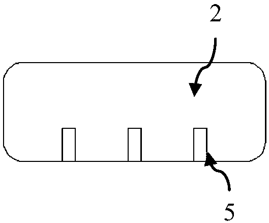
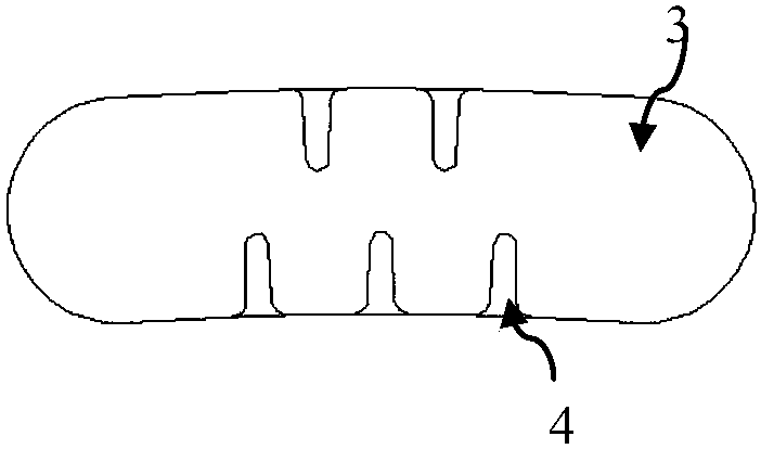
The invention provides a motor with a cooling duct. The motor is a totally enclosed forced air-cooled traction motor. The motor comprises a motor inlet, a motor outlet and a stator. A number of statorcooling ducts are arranged in a circumferential direction in the stator. The stator cooling ducts are respectively communicated with the motor inlet and the motor outlet. A number of turbulence blocks are arranged on the inner wall of the stator cooling ducts. The invention is further applicable to a variety of other motors. The turbulence blocks are arranged in the cooling ducts, which enhancesthe disturbance to a cooling medium, exacerbates the irregular change of a fluid, and enhances the pulsation of fluid particles in all directions in the cooling ducts. The fluid turbulence is enhanced. The convection heat transfer coefficient of the side of the cooling ducts is increased, and the heat transfer rate is increased. The weight of the motor can be effectively controlled, which is conducive to lightweight design.

Description

Technical field [0001] The invention relates to a cooling structure, in particular to a motor with a cooling pipe. Background technique [0002] With the acceleration of the scale of my country's industrial industry, and people's increasing attention to energy and the environment, the single-machine capacity of the drive motor is increasing, and the motor is developing in the direction of miniaturization, light weight and high power density. However, as the single motor capacity increases, its heating will become more serious, which becomes an obstacle to the growth of the limited motor capacity. [0003] When the motor is running, losses are generated, which are converted into heat energy and taken away by the motor cooling system, and at the same time, the temperature of each part of the motor is increased. Excessive heating of the motor leads to an increase in temperature rise, which will directly affect the life of the insulation system used by the motor, which is related to t...

Claims


Application Information

Patent Timeline
IPC IPC(8): H02K1/20H02K1/32H02K5/20
Inventor 杨金霞邹煜林盛振强符敏利史文波崔龙史俊旭胡勇峰罗英露井睿康
Owner CSR ZHUZHOU ELECTRIC LOCOMOTIVE RES INST
Learn More