Programmable electric displacement or rotary execution device
An actuator and electric technology, applied in the direction of electromechanical devices, electric components, electrical components, etc., can solve the problems of low reliability, high application cost, poor precision, etc., and achieve the effect of high precision, low application cost and simple control
- Summary
- Abstract
- Description
- Claims
- Application Information
AI Technical Summary
Problems solved by technology
Method used
Image


Examples
Embodiment 1
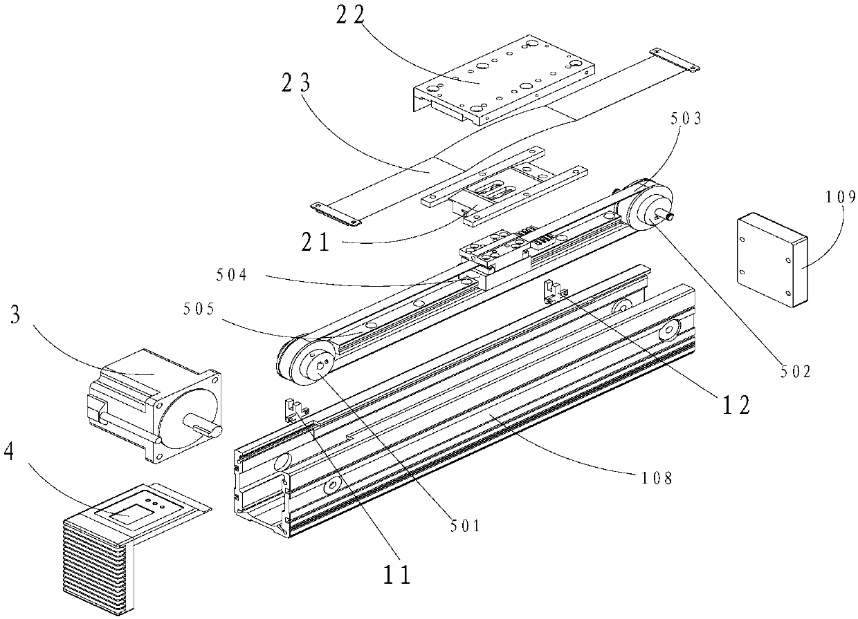
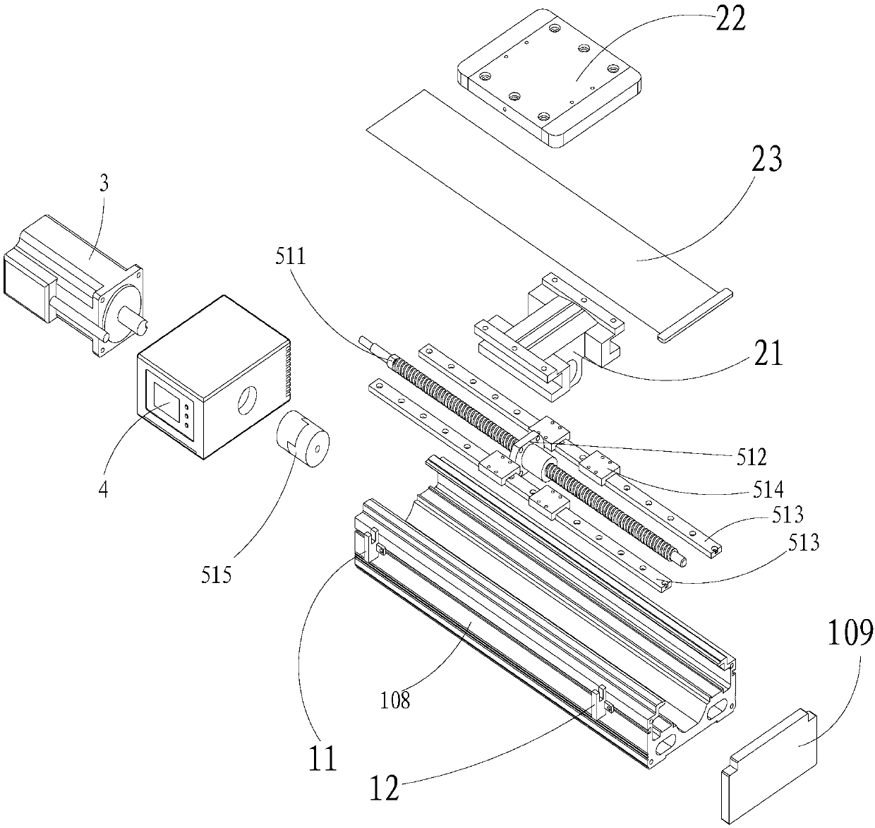
[0050] Specifically, the displacement actuator 2 includes a sliding platform 21 slidably connected to the side of the device body 1 and a sliding platform 22 connected to the sliding platform 21 . A dust-proof assembly (dust-proof belt) 23 may be arranged between the slide table connecting plate 21 and the slide table 22 .
[0051] In Embodiment 1, it may include but not limited to the following application methods:
[0052] The control signals of cylinder mode and step mode in all embodiments, and the start signal of programming mode operation are the START (start signal) of the control signal input circuit in the circuit diagram. See the definition of each input and output port in the explanatory circuit diagram for details.
[0053] 1. Cylinder mode: the high and low levels of the control signal received by the programmable input and output interface 41 are equivalent to the power-on and power-off of the solenoid valve of the cylinder. When the level is high, the slide ta...
Embodiment 2
[0062] Such as Figure 4 As shown, the displacement actuator 2 is a piston rod 202 pierced through the end surface of the device body 1. In this embodiment, the actuator can be used as a programmable electric piston cylinder. Its motor controller 4 has a programmable input and output (I / O) interface, and simple programming through a display interface and manipulation keys can realize automatic control of displacement and I / O.
[0063] Specifically, such as Figure 7 with Figure 8 As shown, a reinforced guide slide structure may also be provided between the piston rod 202 and the device body 1, the reinforced guide slide structure includes a reinforced guide rail 291 arranged on the outside of the device body 1, a reinforced slider 292 slidably connected to the reinforced guide rail 291 at one end, The other end of the reinforcing slider 292 is fixedly connected to the piston rod 202 .
[0064] In the second embodiment, it may include but not limited to the following applic...
Embodiment 3
[0073] Such as Figures 9 to 11, the shift actuator 2 is a claw plate 61, the claw plate 61 can be connected to the device body 1 through a cam structure 62, a connecting rod bearing 63 is connected between the cam structure 62 and the claw plate 61, and the motor controller 4 can be used as a housing (device body 1), and the housing is connected with a front cover 64 and a rear cover 65. The transmission part is connected between the claw plate 61 and the output shaft of the motor 3 . The transmission part can be a shaft coupling 66, and the output shaft side of the shaft coupling 66 or the motor can be provided with an origin detection switch 67. The actuator can be used as a programmable electric finger, which can control the clamping width and clamping torque, and the programmable control input and output interface (I / O), which not only solves the problem of poor control accuracy, low reliability and uncontrollable clamping width of pneumatic fingers It also solves the d...
PUM
 Abstract
Description
Claims
Application Information
 - R&D Engineer
- R&D Manager
- IP Professional
- Industry Leading Data Capabilities
- Powerful AI technology
- Patent DNA Extraction
Browse by: Latest US Patents, China's latest patents, Technical Efficacy Thesaurus, Application Domain, Technology Topic.
© 2024 PatSnap. All rights reserved.Legal|Privacy policy|Modern Slavery Act Transparency Statement|Sitemap