Frequency-locking ring-based motor control method and device

A technology of motor control and frequency locking loop, applied in the direction of excitation or armature current control, etc., can solve the problem that the zoom motor cannot be used for accurate positioning, and the motor cannot be determined, so as to achieve miniaturization, achieve precise zoom, and ensure smooth work. Effect

Inactive Publication Date: 2018-01-23
深圳市显色科技有限公司
View PDF5 Cites 0 Cited by
  • Summary
  • Abstract
  • Description
  • Claims
  • Application Information

AI Technical Summary

Problems solved by technology
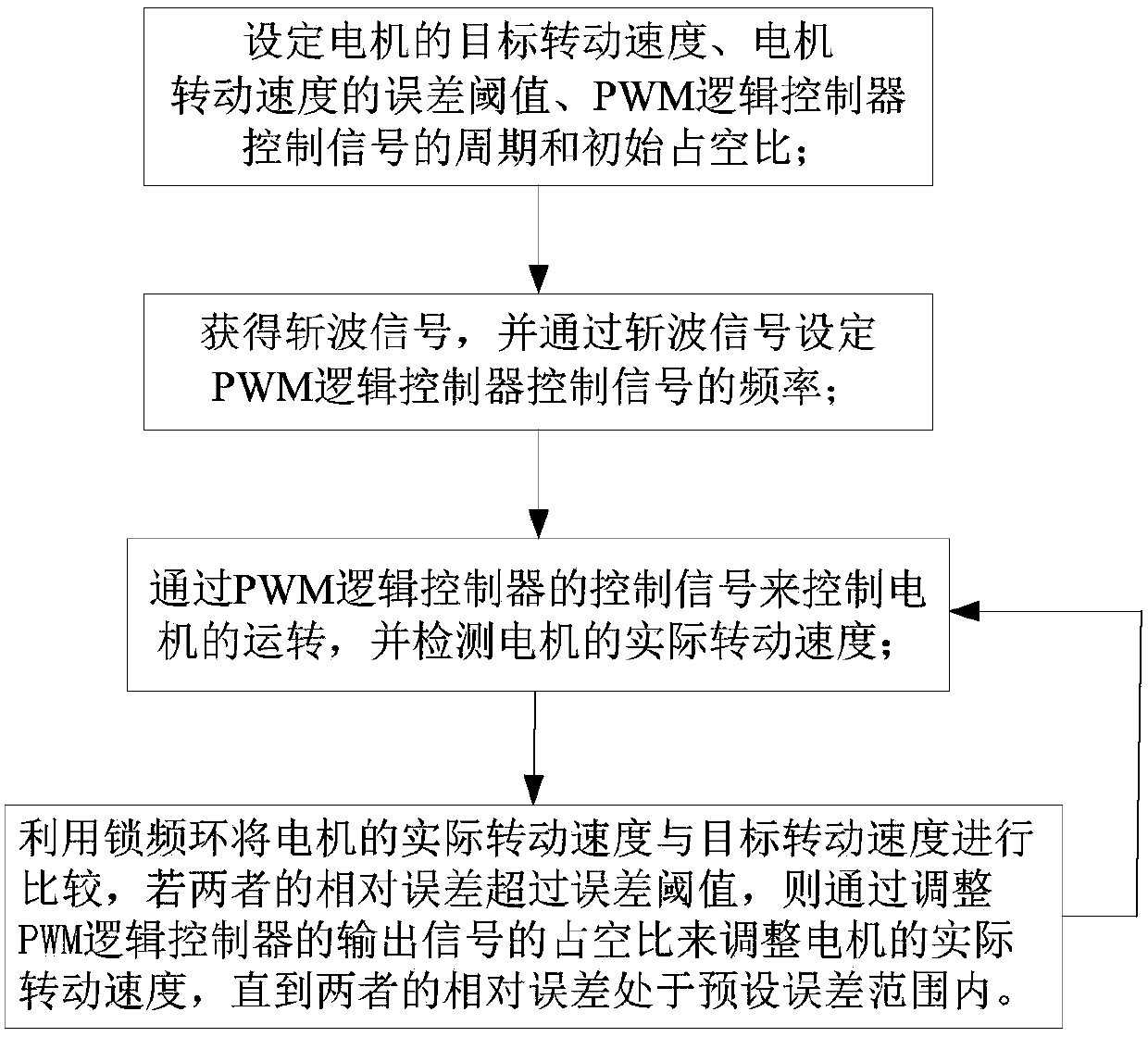
The disadvantage of this driving method is that it is impossible to determine whether the actual speed of the motor is consistent with the designed target speed, and it cannot be used for accurate positioning in the zoom motor

Method used


Image

  • Frequency-locking ring-based motor control method and device
  • Frequency-locking ring-based motor control method and device
  • Frequency-locking ring-based motor control method and device

Examples


Embodiment Construction

[0036] First of all, the frequency lock loop (FLL, Frequency Lock Loop) is essentially an automatic frequency fine-tuning circuit used dynamically, and it is a typical automatic control loop. The characteristics of an automatic control loop not only depend on the number of loops, that is, the number of poles of the transfer function, but also on the loop type. The so-called "type" here refers to the order of the loop without static error, that is, the number of poles of the transfer function at the origin. In a physical sense, it refers to the number of ideal integrators (transfer function 1 / S) included in the loop. . Most of the frequency-locked loops currently in use are digital frequency-locked loops, and their design generally includes filters, frequency detectors, accumulators, and digital voltage-controlled oscillators. Its transfer function is 1 / S, so a general digital frequency-locked loop can be designed as a first-order loop without static error.

[0037] The present ...


PUM


Abstract

The invention discloses a frequency-locking ring-based motor control method. The method comprises the following steps of setting a target rotational speed of a motor, an error threshold of the motor rotational speed and period and an initial duty ratio of a control signal of a pulse width modulation (PWM) logic controller; acquiring a chopping signal, and setting a frequency of the control signalof the PWM logic controller according to the chopping signal; controlling the rotation of the motor according to the control signal of the PWM logic controller, and detecting an actual rotational speed of the motor; and comparing an actual rotational speed with the target rotational speed of the motor by a frequency-locking ring, and adjusting the actual rotational speed of the motor by adjustingthe duty ratio of the control signal of the PWM logic controller until the relative error between the actual rotational speed and the target rotational speed does not exceed the error threshold if therelative error between the actual rotational speed and the target rotational speed exceeds the error threshold. The invention also discloses a corresponding device. By the method, the function of accurate focusing of the motor can be achieved by the DC motor, so that the miniaturization of the motor is achieved.

Description

Technical field [0001] The invention belongs to the field of motor control, and in particular relates to a motor control method and device based on a frequency locked loop. Background technique [0002] In the design of the DC motor drive circuit, for unidirectional motor drive, just use a high-power transistor or field effect tube or relay to directly drive the motor. When the motor needs to rotate in both directions, you can use 4 power components. Full bridge circuit or use a double pole double throw relay. If you do not need to adjust the speed, just use a relay, but if you need to adjust the speed, you can use switching elements such as transistors, field effect tubes to achieve PWM (pulse width modulation) speed adjustment. [0003] However, in the ordinary PWM drive mode, the duty cycle of the PWM, the motor direction when the PWM signal is high, and whether the motor is in the high-impedance state or the brake state when the PWM signal is low are completely set by the regi...

Claims


Application Information

Patent Timeline
IPC IPC(8): H02P7/28
Inventor 魏荣峰谢飞赵春波黄涛涛陈靖文
Owner 深圳市显色科技有限公司
Why Eureka
Try Eureka