Magnetic coupling mechanism applied to wireless charging system of electric vehicle

A technology for wireless charging and electric vehicles, which is applied in electric vehicles, battery circuit devices, current collectors, etc., can solve the problems of reduced energy transmission efficiency of the system, achieve improved energy transmission efficiency, strong lateral offset capability, and ensure power and efficiency effect

Inactive Publication Date: 2018-01-26
HARBIN INST OF TECH +1
View PDF4 Cites 4 Cited by
  • Summary
  • Abstract
  • Description
  • Claims
  • Application Information

AI Technical Summary

Problems solved by technology

[0004] The present invention aims to solve the problem of system energy transmission efficiency reduction caused by inaccurate parking positions during static charging of electric vehicles. The present invention provides a magnetic coupling mechanism applied to electric vehicle wireless charging systems

Method used


Image

  • Magnetic coupling mechanism applied to wireless charging system of electric vehicle
  • Magnetic coupling mechanism applied to wireless charging system of electric vehicle
  • Magnetic coupling mechanism applied to wireless charging system of electric vehicle

Examples


specific Embodiment approach 1

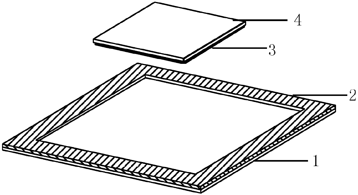
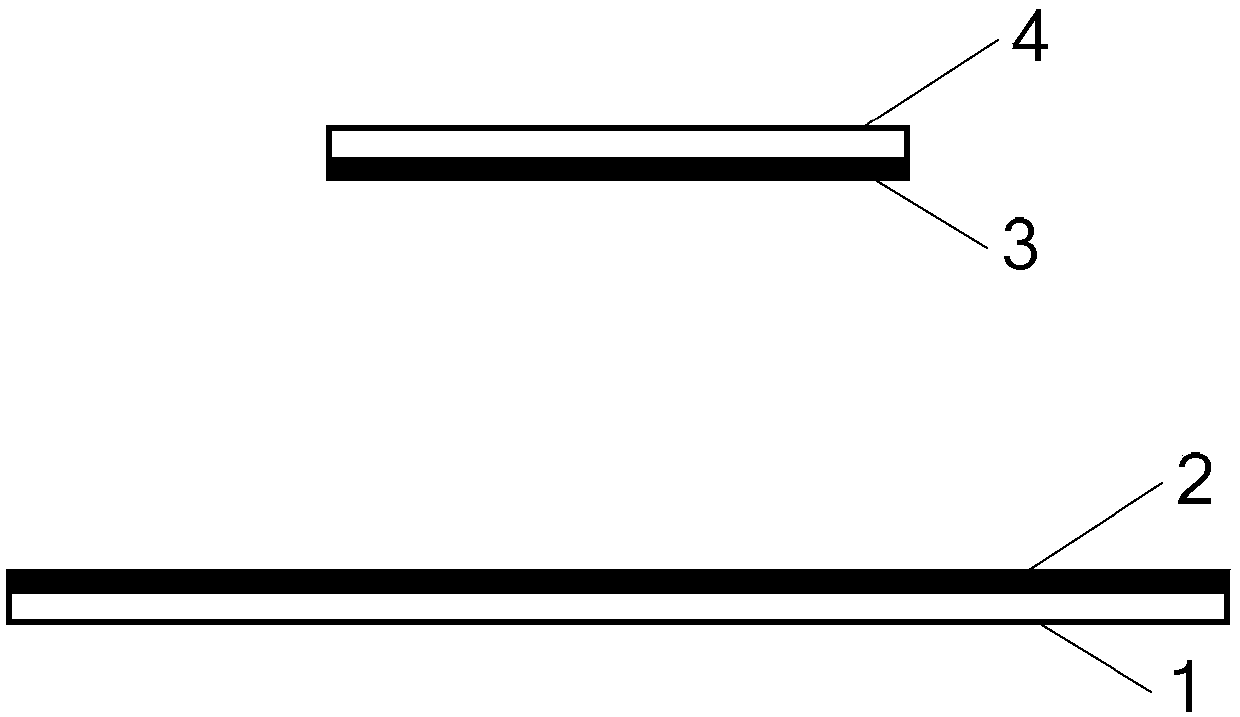
[0019] Specific implementation mode one: see Figure 1 to Figure 3 This embodiment is described. The magnetic coupling mechanism applied to the electric vehicle wireless charging system described in this embodiment includes a transmitting end and a receiving end, the transmitting end is located below the receiving end, and the two are arranged opposite to each other for magnetic coupling;

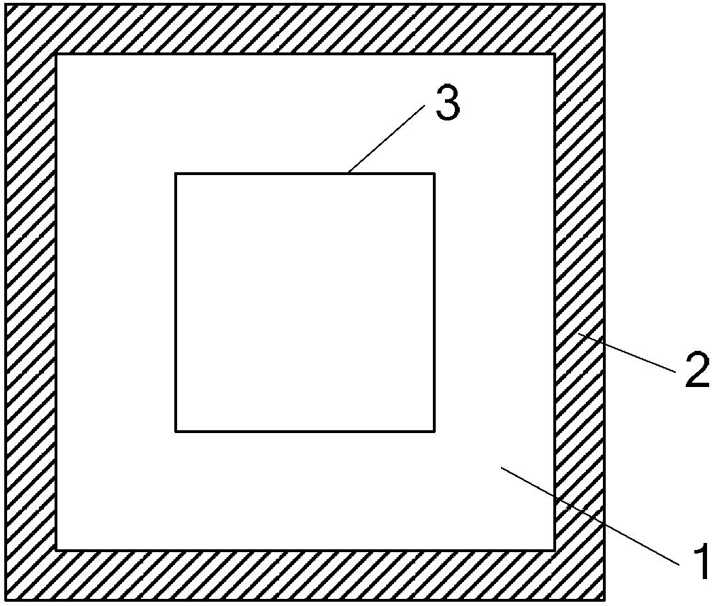
[0020] The transmitting end includes a rectangular transmitting magnetic core 1 and a transmitting coil 2 composed of m×m transmitting flat plates; the transmitting coil 2 is evenly coiled on the transmitting flat plates at the positions of the four borders of the rectangular transmitting magnetic core 1; m is an integer greater than 1;

[0021] The receiving end includes a rectangular receiving core 3 and a receiving coil 4 composed of n×n receiving plates; the receiving coil 4 is evenly coiled on the receiving plates at the four borders of the rectangular receiving core 3; n is an integer ...

specific Embodiment approach 2

[0023] Specific implementation mode two: see Figure 1 to Figure 3 This embodiment is described. The difference between this embodiment and the magnetic coupling mechanism applied to the electric vehicle wireless charging system described in the first embodiment is that the transmitting coil 2 and the receiving coil 4 are realized by using litz coils.

specific Embodiment approach 3

[0024] Specific implementation mode three: see Figure 1 to Figure 3 Describe this embodiment. The difference between this embodiment and the magnetic coupling mechanism applied to the electric vehicle wireless charging system described in Embodiment 1 is that the transmitting coil 2 is wound along the frame of the rectangular transmitting magnetic core 1 from outside to inside. become.


PUM


Abstract

The invention relates to a magnetic coupling mechanism applied to a wireless charging system of an electric vehicle, and belongs to the technical field of wireless electric energy transmission. The problem of low transmission efficiency of system energy due to the inaccurate parking position when the electric vehicle is charged in a static state is solved. The mechanism comprises a transmission terminal and a receiving terminal, the transmission terminal is located below the receiving terminal, and the transmission terminal and the receiving terminal are oppositely arranged and conduct magnetic coupling; the transmission terminal comprises a rectangle transmission magnetic core and a transmission coil which are composed of m*m transmission flat plates; the transmission coil evenly winds the transmission flat plates on four frames of the rectangle transmission magnetic core; m is an integer which is larger than 1; the receiving terminal comprises a rectangle receiving magnetic core anda receiving coil which are composed of n*n receiving flat plates; the receiving coil evenly winds the receiving flat plates on four frames of the rectangle receiving magnetic core; n is an integer which is larger than 1. The magnetic coupling mechanism is mainly applied to wireless electric energy transmission.

Description

technical field [0001] The invention belongs to the technical field of wireless power transmission. Background technique [0002] At present, there are two major bottlenecks in the development of electric vehicles. One is the battery on the vehicle. From the perspective of recent technology, there are many problems such as volume, weight, price, material, safety, charging speed, and lifespan. In addition, the production of batteries The process is a process of high pollution, resource consumption, and damage to the ecological environment. These characteristics bring difficulties to the industrialization of electric vehicles; the second is the problem of charging infrastructure on the ground. On the one hand, due to the long charging time, a large amount of charging or replacement is required. Electric facilities bring great difficulties to municipal construction. These facilities need to occupy a large amount of ground area, which is not conducive to unified management and h...

Claims


Application Information

Patent Timeline
Patent Type & Authority Applications(China)
IPC IPC(8): B60L11/18H02J50/12H02J7/00
CPCY02T10/70
Inventor 朱春波李振杰董帅宋凯逯仁贵魏国
Owner HARBIN INST OF TECH
Why Eureka
Try Eureka