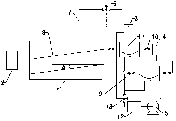
A negative pressure liquefied gas preparation process
A technology of liquefied gas and preparation process, which is applied to equipment discharged from pressure vessels, pressure vessels, mechanical equipment, etc., which can solve the problems of increasing equipment complexity, energy consumption, and low mixing efficiency of air and oil, and achieve reduction Volume, reduce energy consumption, improve the effect of preparation efficiency
- Summary
- Abstract
- Description
- Claims
- Application Information
AI Technical Summary
Problems solved by technology
Method used
Image
Examples
Embodiment 1
[0025] Holes with a diameter of 1.0 mm are evenly distributed on the oil-gas mixing tube 8, and the density of the holes on the oil-gas mixing tube 8 is 3 pcs / cm 2 The wall thickness of the oil-gas mixing tube 8 is 2.5 mm; the oil-gas mixing tube 8 is inclined upward from the air inlet end to the other end, and the inclination angle a between the oil-gas mixing tube 8 and the horizontal plane is 10°;
[0026]After the vacuum pump 5 is turned on, the negative pressure buffer box 12 forms a negative pressure. The controller 3 controls each negative pressure pipe electromagnetic valve 13 to open at a certain time interval. The gas is extracted alternately, the space is reduced, and the space in each gas chamber becomes larger, the pressure decreases, the front check valve 9 is opened, and a negative pressure airflow is formed in the oil-gas mixing pipe 8, and air is sucked into the air filter 2 At the same time, the holes on the oil-gas mixing tube 8 suck in liquid light hydrocar...
Embodiment 2
[0028] Holes with a diameter of 0.8 mm are evenly distributed on the oil-gas mixing tube 8, and the density of the holes on the oil-gas mixing tube 8 is 4 pcs / cm 2 The wall thickness of the oil-gas mixing tube 8 is 3mm; the oil-gas mixing tube 8 is inclined upward from the inlet end to the other end, and the inclination angle a between the oil-gas mixing tube 8 and the horizontal plane is 12°;
[0029] After the vacuum pump 5 is turned on, the negative pressure buffer box 12 forms a negative pressure. The controller 3 controls each negative pressure pipe electromagnetic valve 13 to open at a certain time interval. The gas is extracted alternately, the space is reduced, and the space in each gas chamber becomes larger, the pressure decreases, the front check valve 9 is opened, and a negative pressure airflow is formed in the oil-gas mixing pipe 8, and air is sucked into the air filter 2 At the same time, the holes on the oil-gas mixing tube 8 suck in liquid light hydrocarbons a...
Embodiment 3
[0031] Holes with a diameter of 0.5 mm are evenly distributed on the oil-gas mixing tube 8, and the density of the holes on the oil-gas mixing tube 8 is 5 pcs / cm 2 The wall thickness of the oil-gas mixing tube 8 is 2 mm; the oil-gas mixing tube 8 is inclined upward from the inlet end to the other end, and the inclination angle a between the oil-gas mixing tube 8 and the horizontal plane is 10°;
[0032] After the vacuum pump 5 is turned on, the negative pressure buffer box 12 forms a negative pressure. The controller 3 controls each negative pressure pipe electromagnetic valve 13 to open at a certain time interval. The gas is extracted alternately, the space is reduced, and the space in each gas chamber becomes larger, the pressure decreases, the front check valve 9 is opened, and a negative pressure airflow is formed in the oil-gas mixing pipe 8, and air is sucked into the air filter 2 At the same time, the holes on the oil-gas mixing tube 8 suck in liquid light hydrocarbons ...
PUM
 Abstract
Description
Claims
Application Information
 - R&D
- Intellectual Property
- Life Sciences
- Materials
- Tech Scout
- Unparalleled Data Quality
- Higher Quality Content
- 60% Fewer Hallucinations
Browse by: Latest US Patents, China's latest patents, Technical Efficacy Thesaurus, Application Domain, Technology Topic, Popular Technical Reports.
© 2025 PatSnap. All rights reserved.Legal|Privacy policy|Modern Slavery Act Transparency Statement|Sitemap|About US| Contact US: help@patsnap.com

