
Fiber laser hydrophone and manufacturing method thereof

A fiber laser and hydrophone technology, applied in instruments, measuring devices, measuring ultrasonic/sonic/infrasonic waves, etc., can solve problems such as reducing the diameter of hydrophones, achieve small mechanical impedance, strong absorption capacity, and enhanced stability Effect

Active Publication Date: 2018-01-26
BEIJING INST OF AEROSPACE CONTROL DEVICES
View PDF4 Cites 14 Cited by
  • Summary
  • Abstract
  • Description
  • Claims
  • Application Information

AI Technical Summary

Problems solved by technology

[0003] The purpose of the present invention is to overcome the above-mentioned defects of the prior art, and to provide a fiber laser hydrophone, which adds two elastic diaphragms in the structure, and specially designs the structural shape of the elastic diaphragms, It enables the hydrophone to better pick up low-frequency sound signals, has a stronger ability to absorb the energy generated by acceleration, and can more effectively consume the kinetic energy generated by acceleration, which is conducive to suppressing the acceleration response, and adapts to the thin line of the hydrophone in practical applications. While ensuring high sensitivity at low frequencies, the diameter of the hydrophone is reduced, making it more suitable for use in ultra-fine hydrophone array systems

Method used


Image

  • Fiber laser hydrophone and manufacturing method thereof
  • Fiber laser hydrophone and manufacturing method thereof
  • Fiber laser hydrophone and manufacturing method thereof

Examples


Embodiment Construction

[0039] Below in conjunction with accompanying drawing and specific embodiment the present invention is described in further detail:

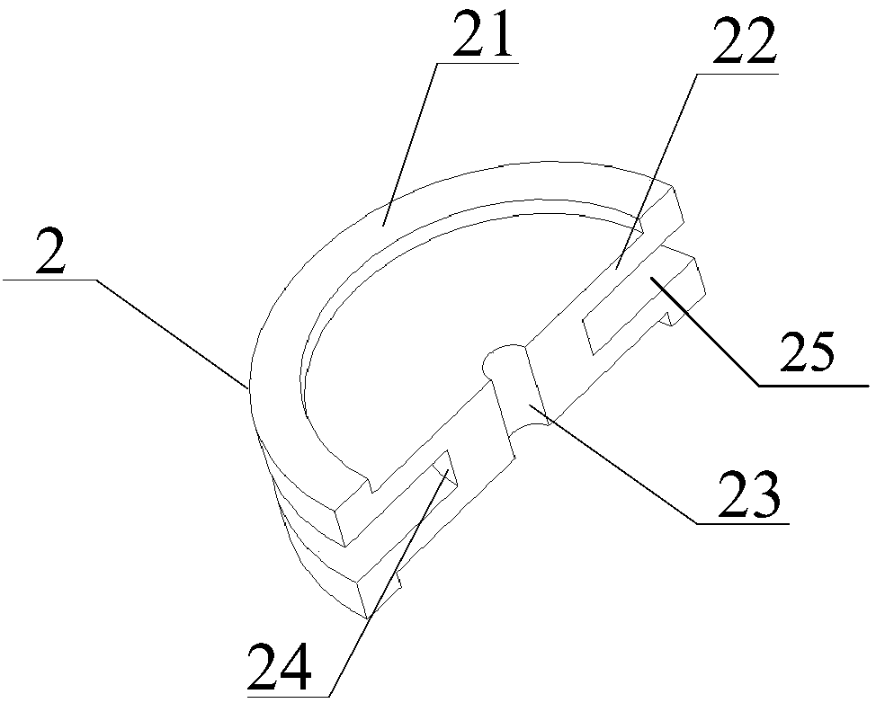
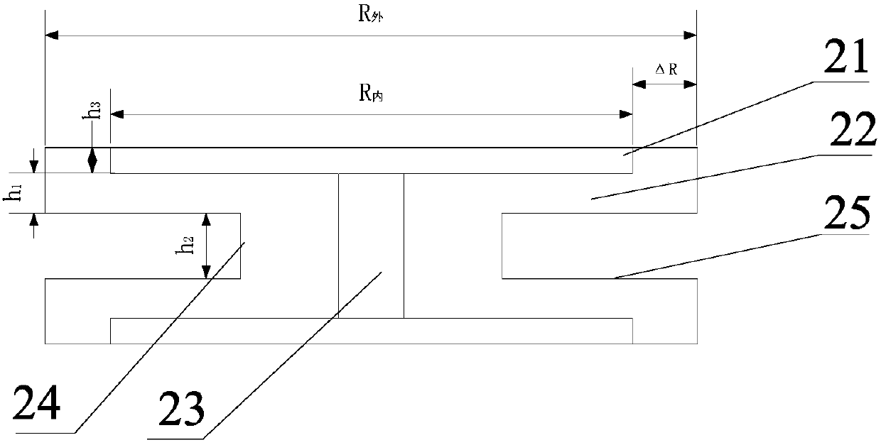
[0040] like figure 1 Shown is a schematic cross-sectional view of the ultra-fine fiber laser hydrophone of the present invention, as can be seen from the figure, the ultra-fine fiber laser hydrophone of the present invention includes an optical fiber 1, two elastic diaphragms 2, a cylinder body, a terminal 5 and a sheath 7. like figure 2Shown is the schematic diagram of the I-shaped diaphragm of the ultra-fine fiber laser hydrophone of the present invention. It can be seen from the figure that the elastic diaphragm 2 includes an upper diaphragm 22, a lower diaphragm 25 and a support column 24, wherein the support column 24 is located on the upper diaphragm. 22 and the lower diaphragm 25, and the upper diaphragm 22 and the lower diaphragm 25 are connected as one. A fiber hole 23 is provided on the elastic diaphragm 2, and the fiber hole 23 is...


PUM


Abstract

The invention relates to a fiber laser hydrophone. The fiber laser hydrophone comprises a fiber containing an active fiber grating, two elastic films, a cylinder, an end head and a sheath, wherein theelastic films comprise upper films, lower films and supporting columns, the elastic films are provided with through fiber holes, the through fiber holes are through holes penetrating through the upper films, the lower films and the supporting columns, and the two elastic films are respectively connected with two ends of the cylinder. The two elastic films are added to the fiber laser hydrophone,structures of the elastic films are specially designed, low frequency sound signals can be better picked up, absorption capability of energy generated because of acceleration is stronger, kinetic energy generated because of acceleration can be more effectively consumed, inhibition of acceleration response is facilitated, fine linear demands for the fiber laser hydrophone in practical application are adapted, on the condition that low frequency high sensitivity is guaranteed, the diameter is reduced, the fiber laser hydrophone can be better applied to a super-fine hydrophone array system, and the fiber laser hydrophone is suitable for micro underground mobile platforms.

Description

technical field [0001] The invention relates to an optical fiber laser hydrophone and a preparation method, in particular to an ultra-fine optical fiber laser hydrophone and a preparation method, belonging to the technical field of optical fiber sensing. Background technique [0002] The fiber laser hydrophone relies on the "active" fiber grating technology, uses the "active" fiber grating as a sensitive element, writes a fiber Bragg grating with a certain phase shift on the erbium-doped or erbium-ytterbium co-doped fiber to form a distributed feedback fiber laser . The underwater acoustic signal is obtained by detecting the phase shift change caused by the external sound pressure acting on the laser resonator cavity. Since the "distributed feedback fiber laser directly etches the grating on the optical fiber, and its diameter is the diameter of the optical fiber, the fiber laser hydrophone obtained after packaging it not only has the advantages of low frequency, high sensi...

Claims


Application Information

Patent Timeline
Patent Type & Authority Applications(China)
IPC IPC(8): G01H9/00
Inventor 李振赵俊鹏张海岩王学锋于文鹏
Owner BEIJING INST OF AEROSPACE CONTROL DEVICES
Learn More