Centrifugation test clamp with fiber type Y waveguide device
A waveguide device, centrifugal test technology, applied in optical instrument testing, machine/structural component testing, instruments, etc., can solve problems such as fiber breakage and low work efficiency, reduce workload, improve efficiency, and improve test work. The effect of efficiency
- Summary
- Abstract
- Description
- Claims
- Application Information
AI Technical Summary
Problems solved by technology
Method used
Image
Examples
Embodiment 1
[0022] Embodiment 1 The design method of the fixture with optical fiber type Y waveguide device
[0023] First, determine the design specifications of the fixture according to the vulnerable parts of the Y waveguide device
[0024] Determine the contact surface material of the vulnerable part through the vulnerable part of the Y waveguide, determine the size and structure of the fixture according to the size of the product test volume and the clamping requirements of the test equipment, and determine the fixture's weight according to the requirements of the mechanical test on the balance of the fixture and the weight of the fixture. Materials, and structural design based on the above factors.
[0025] Through the statistics of the failure parts of the product during the centrifugal test, the main force-bearing surface of the device during the test, and the state of the product in actual application, determine the fiber root of the Y-waveguide with fiber-optic device, the botto...
Embodiment 2
[0032] Example 2 Centrifugal test fixture with optical fiber Y waveguide device
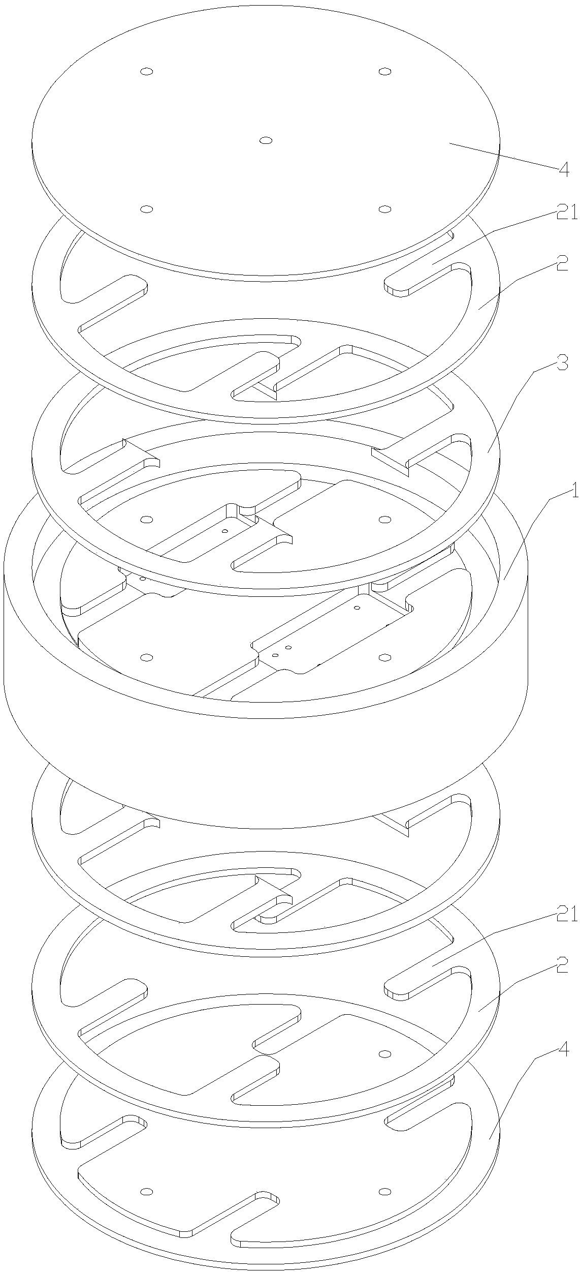
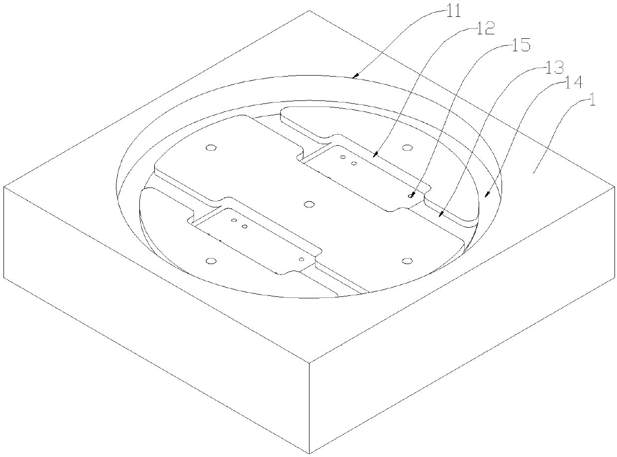
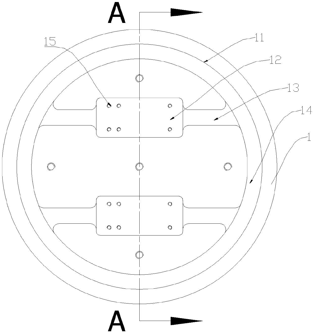
[0033] Such as Figures 1 to 6 As shown: the centrifugal test fixture with fiber-optic Y waveguide device in this embodiment includes a cover plate 4, an outer gasket 2, an inner gasket 3 and a device mounting seat 1 installed sequentially from outside to inside, and the end surface of the device mounting seat 1 There is a columnar groove 11 on it, and at least one retention groove A12 whose size and shape are compatible with the Y waveguide device to be tested is provided on the bottom plane of the groove 11, and the bottom of the retention groove A12 is provided with A plurality of holes 15; a fixing groove B13 for fixing the optical fiber is opened between the middle part of the fixing groove A12 and the bottom edge of the groove 11, the fixing groove A12 and the fixing groove B13 communicate with each other, and the inner gasket 3 is provided with There is a gasket A31 extending toward the r...
PUM
 Abstract
Description
Claims
Application Information
 - R&D Engineer
- R&D Manager
- IP Professional
- Industry Leading Data Capabilities
- Powerful AI technology
- Patent DNA Extraction
Browse by: Latest US Patents, China's latest patents, Technical Efficacy Thesaurus, Application Domain, Technology Topic, Popular Technical Reports.
© 2024 PatSnap. All rights reserved.Legal|Privacy policy|Modern Slavery Act Transparency Statement|Sitemap|About US| Contact US: help@patsnap.com


