Device for compression fatigue test after impact of composite laminate

A composite material layer and fatigue test technology, which is applied in the field of compression fatigue test device for composite material laminates after impact, can solve the problems of peripheral damage, affecting the neutrality of the fixture, and damage at the clamping place, and achieves good neutrality.

Inactive Publication Date: 2018-01-26
SHENYANG AIRCRAFT DESIGN INST AVIATION IND CORP OF CHINA
View PDF3 Cites 6 Cited by
  • Summary
  • Abstract
  • Description
  • Claims
  • Application Information

AI Technical Summary

Problems solved by technology

[0003] In the prior art, there is still no unified standard for the compression fatigue test method of composite laminates with initial low-velocity impact damage. A commonly used method is to directly clamp the specimen on the fatigue testing machine, but due to the The size of the test piece is 150mm long × 100mm wide, and the chuck of the fatigue testing machine often does not have such a large opening size, which requires the test piece to be cut after the low-speed impact test to carry out the fatigue test, and the clamp of the fatigue testing machine The holding force is often too large, and direct clamping will cause the specimen to be easily damaged at the clamping place in the fatigue test
Another kind of test research is completed by modifying the standard of static compression test. By fixing the surrounding of the specimen, the load is introduced into the working section of the specimen by means of end loading. The advantage of this method is that the specimen is After the low-speed impact test, the compression test can be done directly without cutting, but the loading method in this method is to use a "hat" to cover the specimen, and the compression load is transmitted to the specimen through the "hat". In the post-compression residual strength test design, the "hat" responsible for transferring the load is not fixed, and there is an obvious gap between the specimen and the fixture. In the static test, the specimen only needs to bear the loading process once, while in the fatigue test, Repeated friction between the specimen and the fixture will cause the periphery of the specimen to be damaged first, so this method is only suitable for static tests
There is also a shearing method to introduce the load into the working section of the sample. The principle is to transmit the load to the sample in the form of shearing through the conical wedge clamp, but the biggest problem with the cylindrical fixture is its guiding function. There is a large gap between the cylinder and the loading cone, and the thickness, straightness and parallelism of the reinforcing sheet in the fixture will affect the centering of the fixture, so it is easy to produce bending failure during the loading process. The phenomenon of stability, and the type of specimen required by this method is not the size of the specimen used in the low-speed impact test, which requires the specimen to be cut after the low-speed impact test to carry out the fatigue test, which is inconvenient during the test accomplish

Method used


Image

  • Device for compression fatigue test after impact of composite laminate
  • Device for compression fatigue test after impact of composite laminate
  • Device for compression fatigue test after impact of composite laminate

Examples


Embodiment Construction

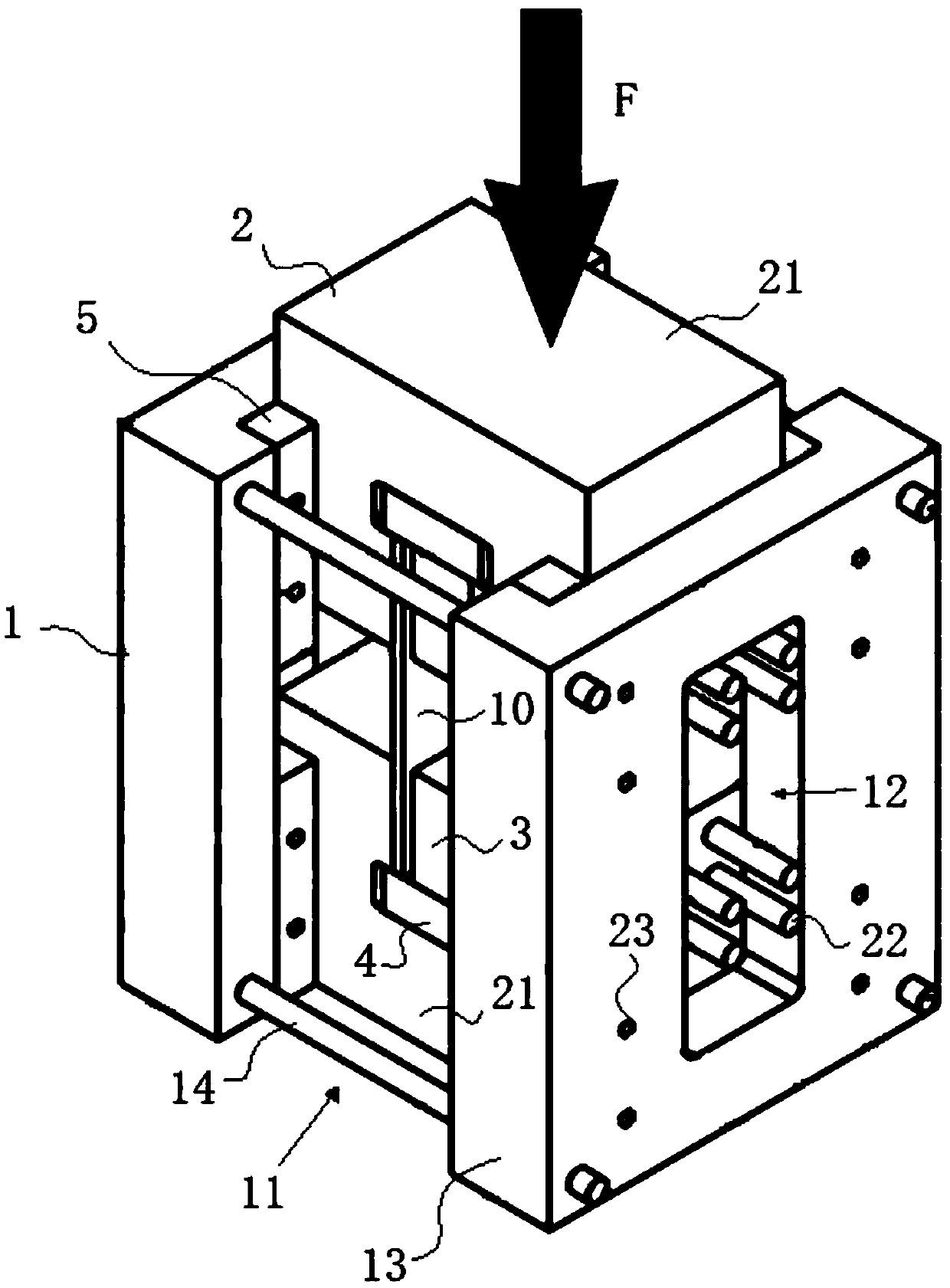
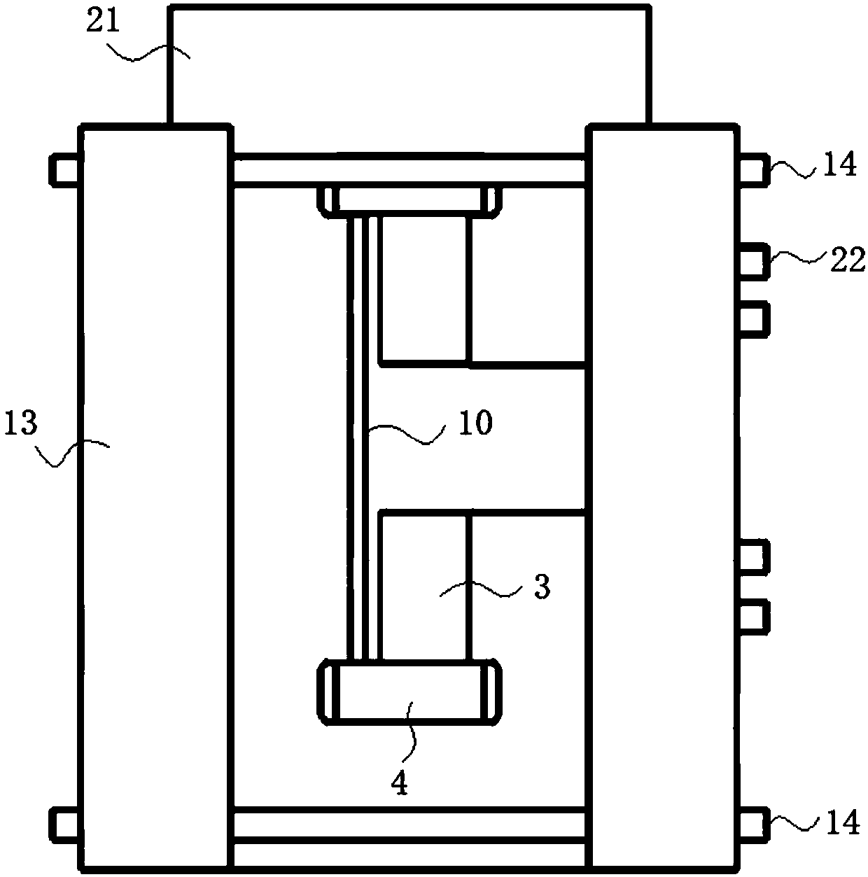
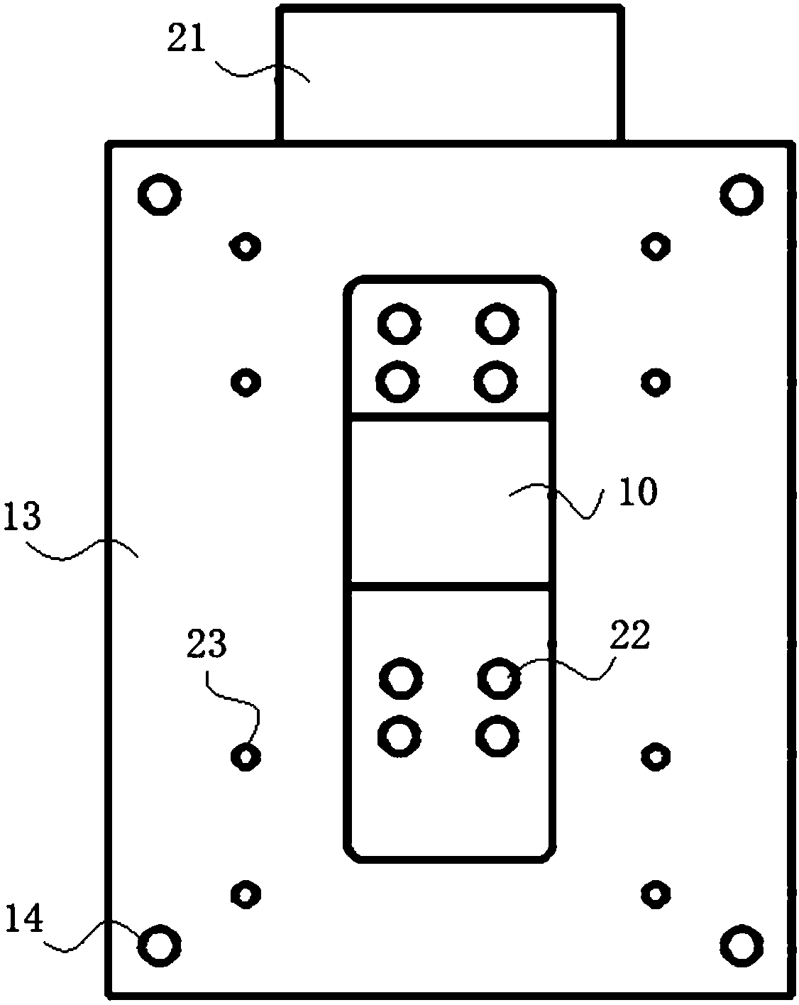
[0032] In order to make the objectives, technical solutions and advantages of the present invention clearer, the technical solutions in the embodiments of the present invention will be described in more detail below in conjunction with the drawings in the embodiments of the present invention.

[0033] In order to overcome the deficiency in the prior art that the composite material laminate specimens after the low-velocity impact test cannot be directly applied to the compression fatigue test, a compression fatigue test device for composite material laminates after low-velocity impact is provided to solve the problem of the initial The problem of fixing specimens in the compression fatigue test of composite laminates with low-speed impact damage makes composite laminates no need to be cut after low-speed impact tests, and can be directly used for compression fatigue tests. In the fatigue test, the laminate test pieces can only Moving along the direction of the compressive load u...


PUM


Abstract

Belonging to the technical field of composite material testing, the invention relates to a device for compression fatigue test after impact of a composite laminate, and the device is used for compression test on a laminate test piece after impact. The device includes: a guide component, which is internally equipped with a guide channel having a guide direction consistent with the loading directionof a loading mechanism; a loading component, which is arranged in the guide channel, and is connected to the loading mechanism for transferring a loading force to the laminate test piece; fixation components, which are fixed to the plane of the laminate test piece to make the panel of the laminate test piece parallel to the loading direction of the loading mechanism. The test device provided by the invention has the advantages that: the composite laminate test piece can be directly used for fatigue test without cutting, and during use of the test device, the laminate test piece has good centering performance, and in the test process, the laminate test piece can undergo compression displacement only under one degree of freedom, thus ensuring no instable failure to the laminate test piece.

Description

technical field [0001] The invention belongs to the technical field of composite material fatigue tests, and in particular relates to a compression fatigue test device and method for composite material laminates after impact. Background technique [0002] Composite laminates have become one of the indispensable materials in the field of modern aerospace due to their advantages such as high specific strength, high specific stiffness, and strong designability. Sensitive, especially after low-velocity impact, the surface of the laminate can hardly be seen to be damaged, but the interior will produce large-area matrix cracking and interlayer delamination. However, under compressive fatigue loads, these damages can be induced and coupled with each other, and the damage evolution and failure mechanism are very complex. At present, with the wide application of composite materials in the main load-bearing structures of aircraft, it is necessary to conduct compression fatigue tests ...

Claims


Application Information

Patent Timeline
Patent Type & Authority Applications(China)
IPC IPC(8): G01N3/00
Inventor 王佳莹卢学峰于春芳苏昱逢
Owner SHENYANG AIRCRAFT DESIGN INST AVIATION IND CORP OF CHINA
Why Eureka
Try Eureka