Check patentability & draft patents in minutes with Patsnap Eureka AI!

Variable speed drive system and method for starting and/or operating variable speed drive system

A drive system, variable technology, applied in the direction of motor speed or torque control, control system, starter of a single synchronous machine, etc., can solve the problem that the speed controllable drive or differential drive cannot be controlled, and the wear of the main drive , impact and other issues, to achieve the effect of favorable and economical design and less wear

Active Publication Date: 2018-01-26
VOITH PATENT GMBH
View PDF12 Cites 2 Cited by
  • Summary
  • Abstract
  • Description
  • Claims
  • Application Information

AI Technical Summary

Problems solved by technology

[0005] A disadvantage of the solutions known from WO 2014 / 169302 A1 and WO 2011 / 000008 A1 is in particular the wear of the main drive, which couples the drive to the output, where this wear is caused by the meshing of the speed-controlled drive or the differential drive of
A further disadvantage is that during main drive start-up, speed-controlled drives or differential drives cannot be controlled and must be mechanically braked or coupled
Another disadvantage is that the changeover between speed-controlled drive or differential drive and main drive is affected by traction interruptions

Method used


Image

  • Variable speed drive system and method for starting and/or operating variable speed drive system
  • Variable speed drive system and method for starting and/or operating variable speed drive system
  • Variable speed drive system and method for starting and/or operating variable speed drive system

Examples


Embodiment Construction

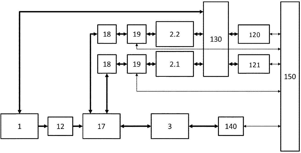
[0071] figure 1 The schematic diagram of the variable speed drive system shown shows a transmission unit 17 having a central input shaft on the driving machine 1 , preferably an electric induction machine, and a central output shaft on the driven machine 3 .

[0072] The transmission unit 17 is preferably designed as a planetary gear having a sun gear 7 , a planet carrier 10 (hereinafter also referred to as “planet”) with planet gears 5 and a ring gear 4 . Thus, coaxiality between the input (driving) and output (driven) shafts is achieved.

[0073] The two regulating machines 2 . 1 , 2 . 2 are coupled to the transmission unit 17 via branched corresponding transmission stages 18 and can thus supply power to the drive machine 1 . Preferably, the two regulating machines 2.1, 2.2 are independent speed controllable electric motors.

[0074] The connection of the input and output shafts to the planetary gears can be done in different ways, thus different types of coincident gears ...


PUM


Abstract

The invention relates to a variable speed drive system. The variable speed drive system has a drive machine (3) and a drive machine (1) which is mechanically coupled or can be coupled to the drive machine (3) by means of a transmission unit (17). Furthermore, at least two regulating machines (2.1, 2.2) are provided which are mechanically coupled or can be coupled to the transmission unit (17) andcan each be operated using one of at least two frequency converters (120, 121). At least one of the at least two frequency converters (120, 121) is electrically connected or can be connected to the drive machine (1) by means of a changeover device (130) in such a way that a connection of the drive machine (1) to at least one electrical supply network (100, 110) is at least temporarily or permanently separable in order to generate an open-loop and / or closed-loop controlled speed change at the drive machine (1). In order to provide a variable speed drive system of this type, in which the wear occurring in the main transmission is kept as low as possible and that the variable speed drive or the differential drive is controllable during the starting of the main drive, and in which, in particular, the changeover between both the variable speed drive or the differential drive and the main drive is free of interruption of traction force.

Description

technical field [0001] The present invention relates to variable speed drive systems. Background technique [0002] Variable speed drive systems are used in industrial applications to better adapt the power to be diverted to the respective process requirements. They are implemented as variable speed configurations, especially in the drive systems of compressors in the oil and gas industry, but also in the drive of high-power fans and pumps in thermal power plants. [0003] For example, a drive system is known from printed publication WO 2014 / 169302 A1 with a constant speed electric main drive, further as an output a rotor, a main drive coupling drive and output, and a variable speed drive coupled also to the main drive. The electric main drive can be started or run with the aid of a speed-controlled drive. The speed-controlled drive is connected to a frequency converter which can be switched to the main drive for starting. Once the nominal speed of the electric main drive...

Claims


Application Information

Patent Timeline
Patent Type & Authority Applications(China)
IPC IPC(8): H02P1/46H02P9/06
CPCH02P9/06H02P1/46H02P5/753
Inventor B·劳特尔J·林登迈尔S·克内尔
Owner VOITH PATENT GMBH
Features
  • R&D
  • Intellectual Property
  • Life Sciences
  • Materials
  • Tech Scout
  • Unparalleled Data Quality
  • Higher Quality Content
  • 60% Fewer Hallucinations
Learn More