Hydraulic assembly

A hydraulic unit and hydraulic technology, applied in the direction of hydraulic steering gear, steering mechanism, fluid steering mechanism, etc., can solve the problems of motor mechanical power limitation, easy failure, and increased damage probability of hydraulic electric steering system, so as to improve reliability The effect of reducing the damage probability

Inactive Publication Date: 2018-01-30
WEBER HYDRAULIK GMBH
View PDF1 Cites 1 Cited by
  • Summary
  • Abstract
  • Description
  • Claims
  • Application Information

AI Technical Summary

Problems solved by technology

This leads to an increased probability of damage to the electrohydraulic steering system
[0004] In the solutions known from the prior art, on the one hand the mechanical power limit of the motor is reached
In addition, the on-board power supply for the vehicle's current supply is prone to failure as it always requires a higher current to provide the required hydraulic power

Method used


Image

  • Hydraulic assembly
  • Hydraulic assembly
  • Hydraulic assembly

Examples


Embodiment Construction

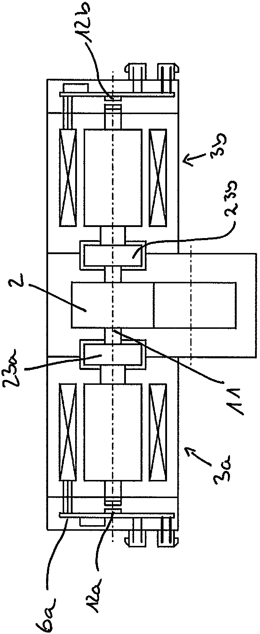
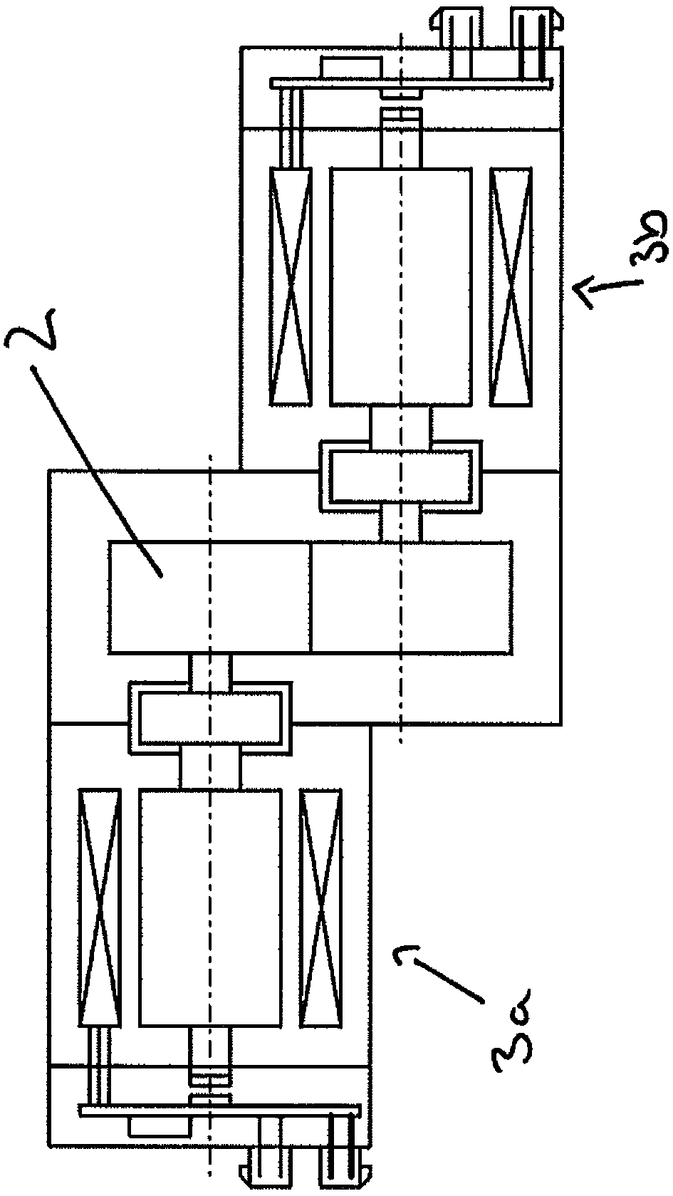
[0056] exist Figure 1-4 In , the same reference numerals represent the same parts or parts with the same function.

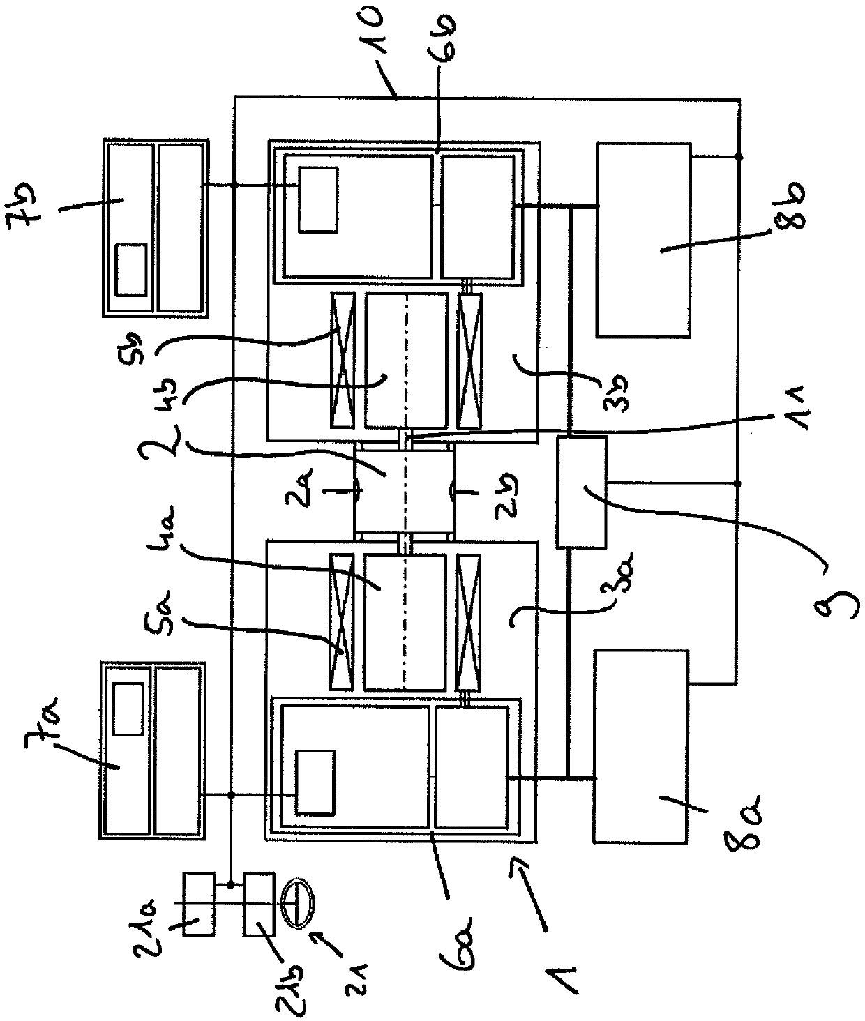
[0057] figure 1 A schematic diagram of a first embodiment of the hydraulic unit of the invention is shown.

[0058] The hydraulic unit 1 comprises a hydraulic pump 2 and two drive motors 3a, 3b. The drive motors 3a, 3b are each designed with a rotor 4a, 4b and a stator 5a, 5b and each include a motor controller 6a, 6b. Here, the two drive motors 3a, 3b are designed as brushless motors.

[0059] In a redundant embodiment, a control circuit 7a, 7b is also provided here for each of the two drive motors.

[0060] The hydraulic pump 2 is configured as a gear pump with a double-side drive structure. Via the two ports 2a, 2b the hydraulic fluid reaches the hydraulic cylinder 25 as Figure 4 shown. The hydraulic pump 2 is arranged between the two drive motors 3a, 3b.

[0061] The hydraulic unit with the two drive motors 3 a , 3 b is supplied by a power supply 8...


PUM


Abstract

A hydraulic drive arrangement (1) for the pressure supply of a hydraulic steering system (20), particularly for construction or agricultural machines, including a hydraulic pump (2) and an electric drive. It is essential that the electric drive is designed in a redundant fashion and has two separately controlled electric drive engines (3a, 3b), which are mechanically coupled via the hydraulic pump(2) in a rigid fashion, and that the separate control circuits (6a, 6b, 7a, 7b) are provided by which a variable load distribution can be specified for the electric drive engines (3a, 3b).

Description

technical field [0001] The invention relates to a hydraulic unit for the pressure supply of hydraulic steering systems, in particular for trucks, construction machines or agricultural machines, which has a hydraulic pump and an electric drive. Background technique [0002] Steering systems in motor vehicles today usually have a hydraulic steering booster. For this reason, a hydraulic steering auxiliary pump is used in the hydraulic steering system to support the steering kinematics. [0003] The hydraulic steering assist pump is usually driven by the internal combustion engine of the motor vehicle. With the increasing electrification of vehicles and energy-saving measures such as start-stop functions, this task is increasingly performed by electric motors. As a result, higher and higher currents are used to provide the required hydraulic power, and the burden and demands on the corresponding vehicle systems (eg on-board power supply and battery) for supplying the electric ...

Claims


Application Information

Patent Timeline
Patent Type & Authority Applications(China)
IPC IPC(8): B62D5/06B62D5/065B62D5/30
CPCB62D5/064B62D3/14B62D5/046B62D5/0487B62D5/065B62D5/30
Inventor 瑙曼·拉尔夫温克勒·托尔斯滕
Owner WEBER HYDRAULIK GMBH
Why Eureka
Try Eureka