Method and system for exhaust aftertreatment

A technology of exhaust system and exhaust flow, which is applied in the direction of exhaust treatment, electronic control of exhaust treatment device, exhaust device, etc., and can solve problems such as boost pressure loss and turbo lag

Inactive Publication Date: 2018-02-02
FORD GLOBAL TECH LLC
View PDF10 Cites 6 Cited by
  • Summary
  • Abstract
  • Description
  • Claims
  • Application Information

AI Technical Summary

Problems solved by technology

Further, positioning the DOC, DPF, and/or SCR catalyst upstream of the exhaust turbine can result

Method used


Image

  • Method and system for exhaust aftertreatment
  • Method and system for exhaust aftertreatment
  • Method and system for exhaust aftertreatment

Examples


Embodiment Construction

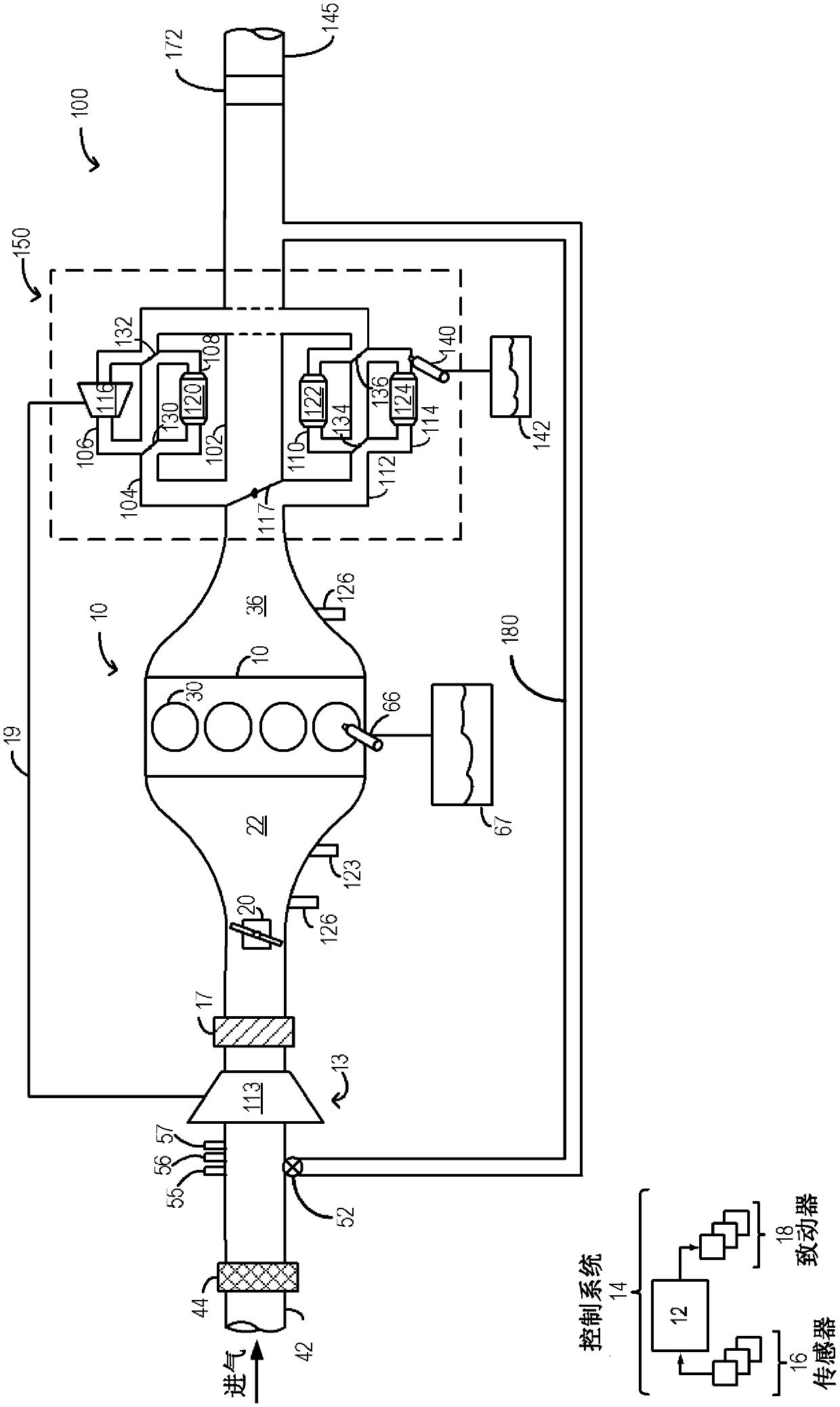
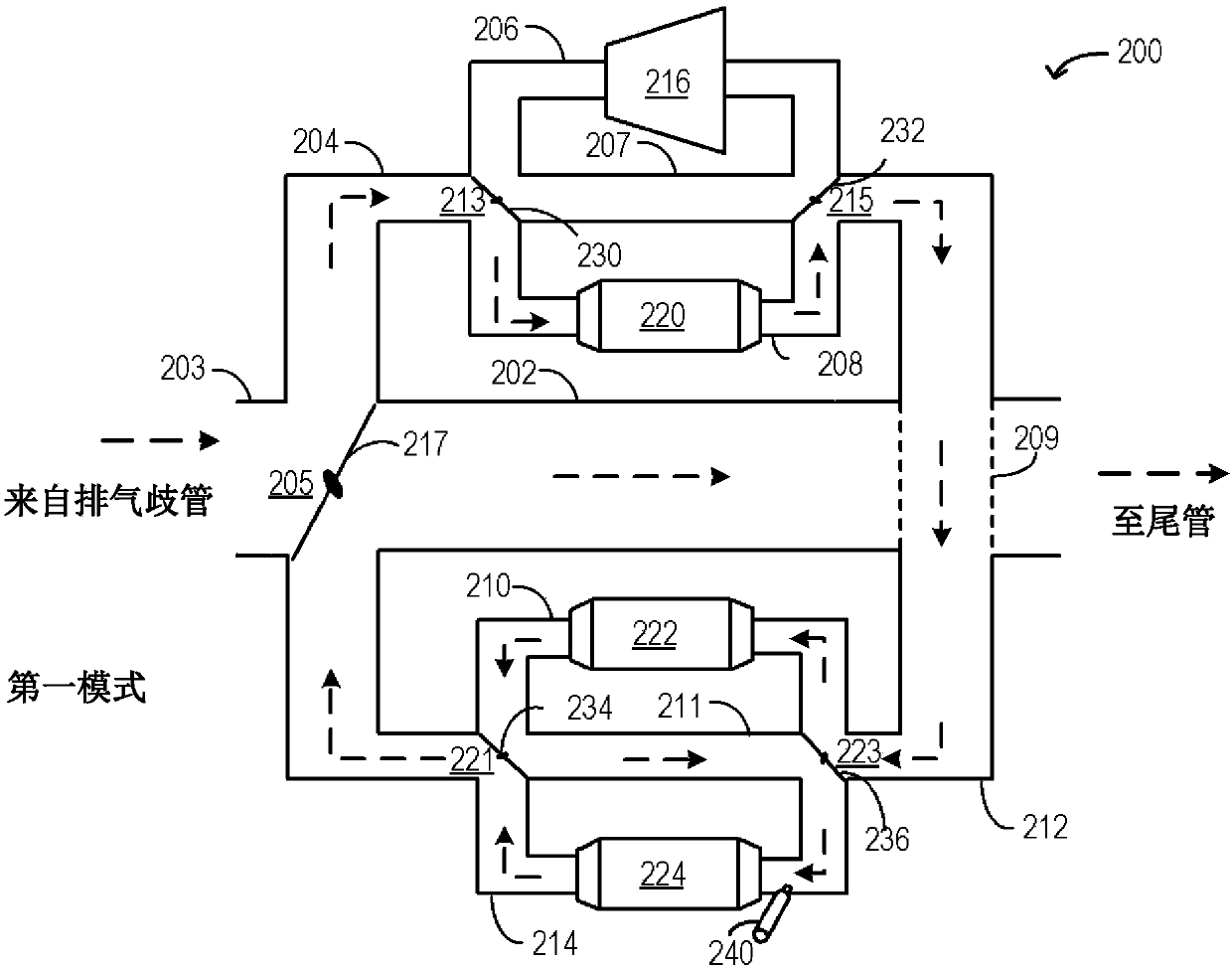
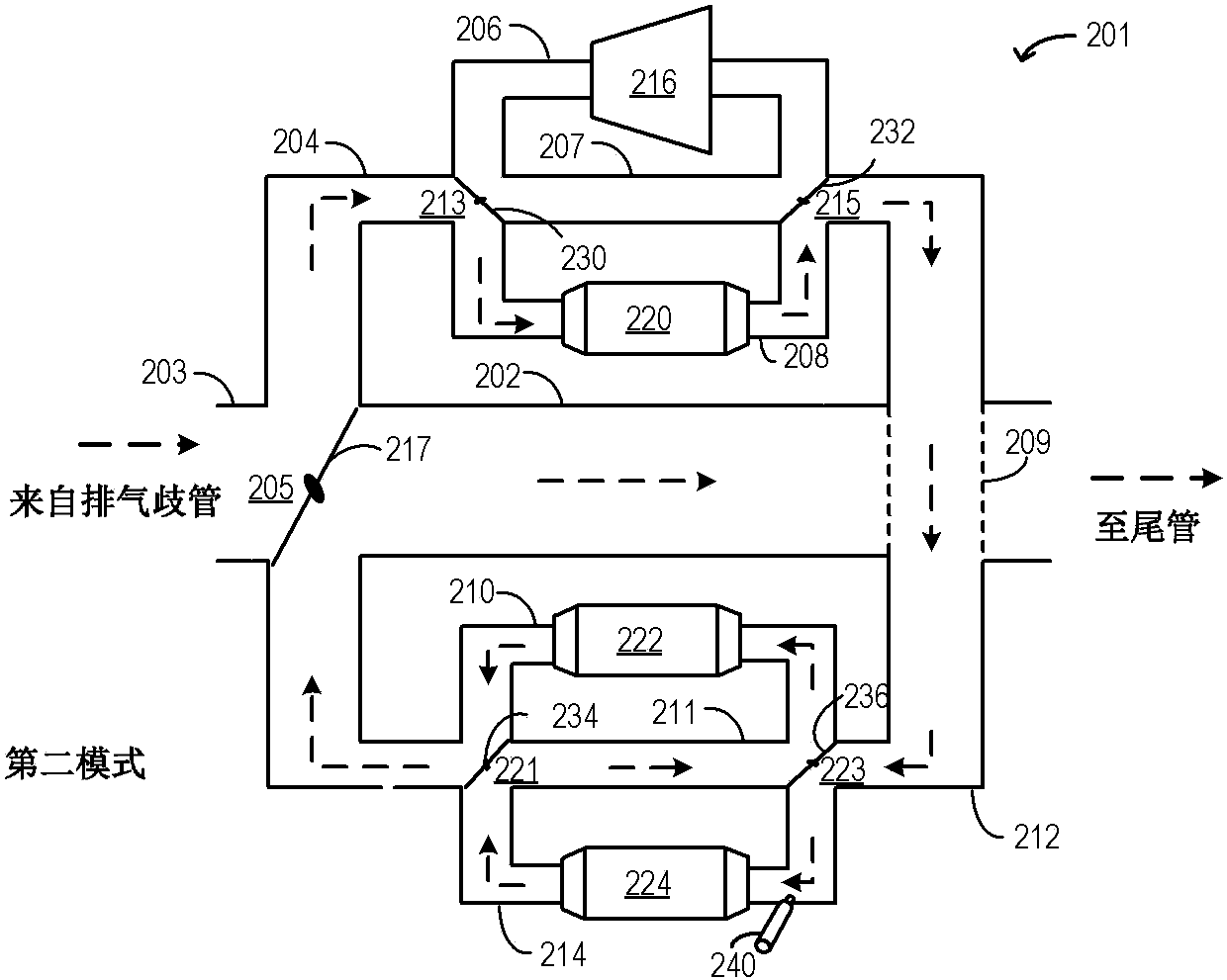
[0028] The following description relates to systems and methods for operating a branch exhaust aftertreatment system to increase the efficiency of exhaust system components and reduce engine emissions. figure 1 An example engine system including a branched exhaust assembly is shown. Different exhaust manifold components, such as the turbo, diesel oxidation catalyst (DOC), diesel particulate filter (DPF), and selective catalytic reduction (SCR) catalyst, may be housed in different branches of the assembly. Figure 7 A cross-sectional view of a DPF showing views of alternating passages. refer to Figure 2A to Figure 2J The different modes of operation of the branch exhaust assembly are detailed. The engine controller can be configured to execute control programs such as image 3 with Figure 4 An example procedure for directing exhaust gas through different branches of a branched exhaust assembly based on the engine operating conditions and temperature requirements of the re...


PUM


Abstract

Methods and systems are provided for reducing engine emissions using a branched exhaust system. In one example, a branched exhaust system may include a plurality of sub-branches each housing a distinct exhaust component, and an order of exhaust flow through each of the exhaust components may be adjusted based on engine operating conditions and temperature demand of the distinct components.

Description

technical field [0001] The present disclosure generally relates to methods and systems for controlling a vehicle engine to increase the efficiency of an exhaust aftertreatment system and reduce engine emissions. Background technique [0002] The engine may operate on an air charge provided via a turbocharger, with an intake compressor driven by an exhaust turbine. However, placing the turbo in the exhaust system can increase engine cold start emissions due to the turbo acting as a radiator. Specifically, engine exhaust heat during engine cold starts may be absorbed at the turbine, thereby reducing the amount of exhaust heat received at downstream exhaust aftertreatment devices. Thus, this delays reaching the light-off temperature at an exhaust catalyst such as a diesel oxidation catalyst (DOC) or a selective catalytic reduction (SCR) catalyst. Additionally, regeneration of particulate filters, such as DPFs, may be delayed. Placing the turbine downstream of the exhaust aft...

Claims


Application Information

Patent Timeline
IPC IPC(8): F01N9/00F01N13/00F02B37/18
CPCF01N9/00F01N9/002F01N2250/02F01N2570/14F02B37/183F01N13/009F01N13/011F01N3/021F01N3/023F01N3/103F01N3/2066F01N2240/36F01N2900/0412F01N2900/08F01N2900/1606F01N2900/1614F02B37/186Y02T10/12Y02T10/40Y02A50/20
Inventor 张小钢
Owner FORD GLOBAL TECH LLC
Why Eureka
Try Eureka