Multi-signal-source frequency and DOA joint detection method and device

A joint detection and multi-source technology, which is applied in the direction of measuring devices, directional devices for determining directions, radio wave measurement systems, etc., can solve problems such as the inability to realize joint estimation of frequency and DOA, and achieve reduced hardware costs, high estimation accuracy, The effect of high measurement accuracy

Active Publication Date: 2018-02-02
TIANJIN UNIV
View PDF3 Cites 12 Cited by
  • Summary
  • Abstract
  • Description
  • Claims
  • Application Information

AI Technical Summary

Problems solved by technology

It should be pointed out that the above sparse arrays cannot realize the joint estimation of frequency and DOA

Method used


Image

  • Multi-signal-source frequency and DOA joint detection method and device
  • Multi-signal-source frequency and DOA joint detection method and device
  • Multi-signal-source frequency and DOA joint detection method and device

Examples


Embodiment 1

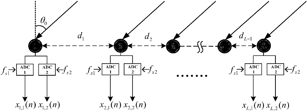
[0053] 101: Set up a sparse linear antenna array containing L array elements, and arrange two ADC samplers at each array element position;

[0054] Among them, starting from a specific moment, the two ADC samplers of each array element are respectively set by f s1 ,f s2 The incident signal is undersampled in parallel at two sampling rates, and the number of snapshots collected by each array element is M f .

[0055] During specific implementation, the sampling rate is set according to requirements in practical applications, which is not limited in this embodiment of the present invention.

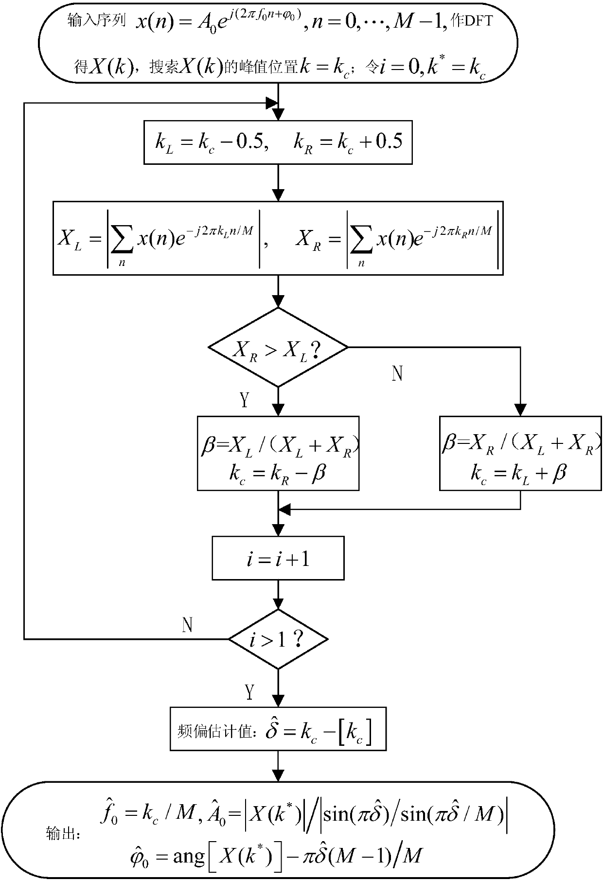
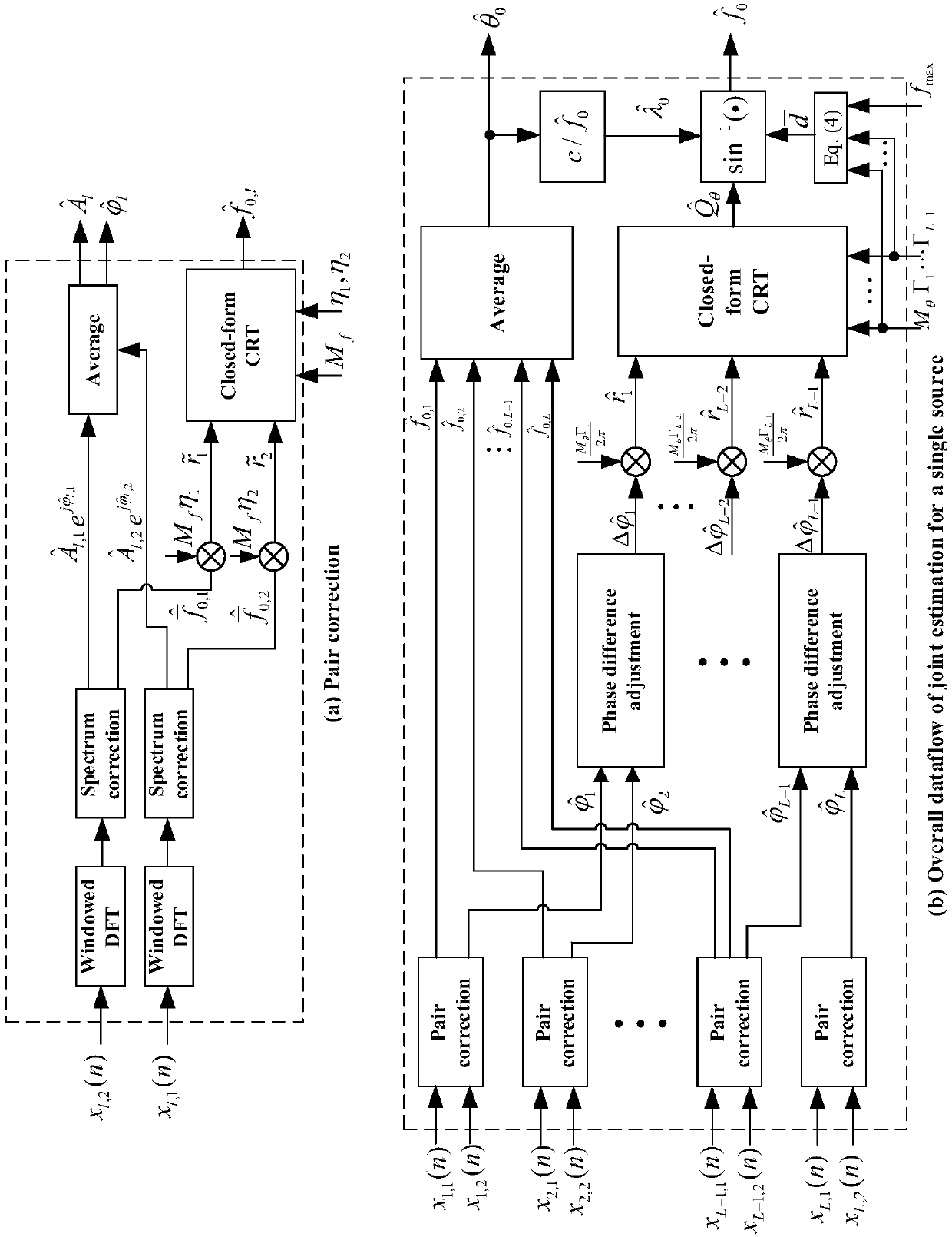
[0056] 102: Do M on the obtained L signal samples f Point DFT, utilizing the Tsui spectral corrector [12] Carry out frequency and phase correction on the DFT results, obtain D sets of frequency, phase, and amplitude parameter sets after correction, and use the parameter sets to construct D direction vectors;

[0057] Wherein, the calibrator is well known to those skilled in the art, an...

Embodiment 2

[0062] The scheme in embodiment 1 is further introduced below in conjunction with specific calculation formulas and examples, see the following description for details:

[0063] 201: Array element structure and signal model;

[0064] Such as figure 1 As shown, a mutually prime sparse array with the number of array elements L is arranged, and two ADC samplers with different sampling rates are arranged at each array element position (the sampling rates are respectively f s1 = M f n 1 ,f s2 = M f n 2 , where η 1 and η 2 are relatively prime integers, M f is a positive integer).

[0065] Suppose a carrier frequency is f 0 The far-field narrowband signal of the angle θ 0 incident on the antenna array, the phase difference of the signal received by the lth array element and the l+1th array element is:

[0066]

[0067] Among them, λ 0 =c / f 0 is the signal wavelength, d l Indicates the array element spacing, and c is the speed of light.

[0068] Due to the high spa...

Embodiment 3

[0139] according to figure 1 The mutually prime sparse array antenna with the number of array elements L=3 is arranged as shown, and the unit wavelength λ=0.15 is set, M θ =2, corresponding to {Γ 1 ,Γ 2}={5,6}, according to formula (5), the array element spacing is d 1 =0.9,d 2 = 0.75. set{η 1 , η 2}={5641,5647}, M f =512, the sampling rates of the corresponding ADC1 and ADC2 are respectively: f s1 =2888192Hz,f s2 =2891264Hz.

[0140] Assuming that 4 far-field narrowband signals are incident on the array, the parameter settings are shown in the table below:

[0141]

[0142] At first the multi-target estimation ability of the present invention is checked, make SNR=25dB, and estimation result is as shown in the table below:

[0143]

[0144] Experimental results show that the present invention can accurately estimate the frequency and DOA of four information sources, and has high estimation accuracy.

[0145] In the following, the parameter estimation performa...


PUM


Abstract

The invention discloses a multi-signal-source frequency and DOA joint detection method and a multi-signal-source frequency and DOA joint detection device. The multi-signal-source frequency and DOA joint detection method comprises the steps of: conducting Mf-point DFT on L paths of signal samples, correcting frequencies and phases of DFT results by using a Tsui spectrum corrector to obtain a parameter group of corrected D groups of frequencies, phases and amplitude values, and constructing D direction vectors by using the parameter group; grouping and matching the D direction vectors accordingto the minimum distance to obtain D pieces of signal source parameter matching information; constructing a frequency remainder group according to the D pieces of signal source parameter matching information, and substituting the frequency remainder group into a closed type robust Chinese remainder theorem (CRT) model for reconstruction, so as to obtain a frequency estimated value; and acquiring L-1 phase differences according to the D pieces of signal source parameter matching information, constructing a phase reminder group, substituting the phase remainder group and a reconstructed module value group into the closed type robust CRT model for reconstruction to obtain an intermediate parameter, and calculating to obtain a DOA estimated value. The multi-signal-source frequency and DOA jointdetection method and the multi-signal-source frequency and DOA joint detection device realize the high-precision frequency and DOA joint estimation of multiple pairs of targets.

Description

technical field [0001] The present invention relates to the technical field of signal analysis and processing, in particular to under-sampling processing based on a new type of mutual prime sparse array under the condition that multiple sources of observations are incident on the array antenna, and spectrum correction and Chinese remainder theorem are repeated. structure, so as to realize the high-precision joint measurement of multi-target frequency and DOA (angle of arrival). Background technique [0002] The frequency and DOA joint estimation of multi-target sources is a research hotspot in the field of array signal processing. [1] ,Wireless communication [2] , electronic warfare and other fields have a wide range of applications. At present, most existing spatial spectrum estimation algorithms are based on subspace decomposition spectrum estimation algorithms (such as MUSIC (Multiple Signal Classification Algorithm), ESPRIT (Rotation Invariant Signal Parameter Estimati...

Claims


Application Information

Patent Timeline
Patent Type & Authority Applications(China)
IPC IPC(8): G01S3/02G01S3/20G01R23/16
CPCG01R23/16G01S3/023G01S3/20
Inventor 黄翔东刘明卓李长滨
Owner TIANJIN UNIV
Why Eureka
Try Eureka