
A three-dimensional reverse time migration imaging method of electromagnetic waves based on high-order time-domain algorithm

A technology of reverse time migration imaging and electromagnetic waves, which is applied in the directions of electromagnetic wave detection, radio wave measurement system, radio wave reflection/re-radiation, etc. It can solve the problems that the basic shape and structure cannot be effectively determined, and improve the imaging effect. Effect

Active Publication Date: 2019-08-20
XIAMEN UNIV
View PDF7 Cites 1 Cited by
  • Summary
  • Abstract
  • Description
  • Claims
  • Application Information

AI Technical Summary

Problems solved by technology

Although the approximate location of the medium can be simply deduced based on its stroke, amplitude and phase data obtained from the received echo electromagnetic signal, its basic shape and structure cannot be effectively determined.

Method used


Image

  • A three-dimensional reverse time migration imaging method of electromagnetic waves based on high-order time-domain algorithm
  • A three-dimensional reverse time migration imaging method of electromagnetic waves based on high-order time-domain algorithm
  • A three-dimensional reverse time migration imaging method of electromagnetic waves based on high-order time-domain algorithm

Examples


specific Embodiment approach

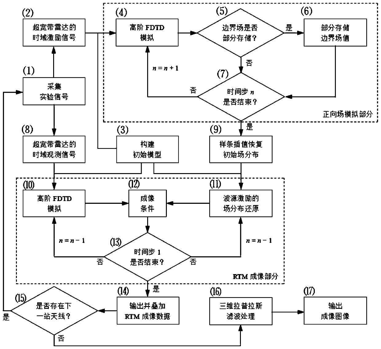
[0065] The present invention proposes an electromagnetic wave three-dimensional reverse time migration imaging method under the high-order time-domain algorithm, and the flow chart of its design scheme can be found in figure 1 , and its block diagram information is as follows:

[0066] (1) Acquisition of experimental signals: If the reverse time migration imaging method is to be realized, the process of acquiring experimental signals is indispensable. It is necessary to process the time-domain signals of each station in the UWB radar system.

[0067] (2) Time-domain excitation signal of ultra-wideband radar: from the collected experimental signal, it is necessary to extract the transmitted signal and perform the corresponding forward field simulation part.

[0068] (3) Construction of initial model: For the forward field simulation part, the process of numerical experiment is involved, and the target of underground detection is also unknown, so the initial model is constructe...


PUM


Abstract

The invention discloses an electromagnetic wave three-dimensional reverse time migration imaging method under a higher-order time domain algorithm, and relates to the computing electromagnetics and broadband radar detection. The method is suitable for the exploration and data collection and imaging of an underground object of a UWB (ultra wide band) radar and a hidden medium region, and is also widely suitable for the geological prospecting, road inspection and through-wall imaging. The forward direction field distribution of a time domain excitation signal received by the UWB radar and the reverse field distribution of a time domain observation signal received by the UWB radar are obtained through a three-dimensional high-order time domain finite difference method and an experiment signaldetected by the UWB radar. The method theoretically overcomes the inclination restriction under the condition that the requirements of the reverse time migration imaging are met, and can achieve theprecise imaging. The method employs the radar signal for the numerical simulation of the reverse time migration imaging simulation of a target region, and can effectively obtain the dynamic information of a to-be-detected object. Compared with a conventional electromagnetic imaging algorithm, the method is higher in imaging resolution, and layers a solid foundation for the discrimination of the to-be-detected object and the parametric inversion.

Description

technical field [0001] The invention relates to computational electromagnetics and broadband radar detection, in particular to an electromagnetic wave three-dimensional reverse time migration imaging method under a high-order time domain algorithm. Background technique [0002] In terms of broad-spectrum electromagnetic technology, the ultra-wideband radar method can effectively estimate the current distribution of underground media. The working principle of ultra-wideband radar is to use one antenna or a combination of multiple antennas to transmit a broadband electromagnetic signal to the target area, and another antenna or combination of multiple antennas to receive the interface reflection and scattering signals from the target to be measured in the target area. When the electromagnetic pulse signal propagates in the target to be measured, its specific path, field strength and waveform profile must change drastically with the specific parameters of the medium and its geo...

Claims


Application Information

Patent Timeline
Patent Type & Authority Patents(China)
IPC IPC(8): G01S13/89G01S13/88G01V3/12
Inventor 柳清伙张玉贤王礼晓冯乃星庄明伟刘海
Owner XIAMEN UNIV
Learn More