
Electrified railway three-phase photovoltaic DC side energy storage system and control method thereof

A technology for electrified railways and energy storage systems, applied in the direction of photovoltaic power generation, electrical components, circuit devices, etc., can solve the problems of high investment cost, maintenance of DC bus voltage, and inadvisability, so as to improve system economy and reduce energy storage capacity , The effect of reducing power waste

Pending Publication Date: 2018-02-02
SOUTHWEST JIAOTONG UNIV
View PDF6 Cites 8 Cited by
  • Summary
  • Abstract
  • Description
  • Claims
  • Application Information

AI Technical Summary

Problems solved by technology

However, due to the vast distribution of my country's railway network in combination with national conditions, most lines are still not busy lines. If the self-use control strategy is adopted, a large-capacity energy storage device must be installed in order to reduce the waste of electricity. At present, the investment cost of energy storage equipment is relatively high, it is clearly not economically advisable to install large-capacity energy storage
The existing technology cannot adapt to the photovoltaic consumption control of most railway lines, that is, according to the real-time operation conditions of the traction load on the railway line, the selection of the operation mode of the photovoltaic storage system cannot achieve reasonable consumption; on the other hand , because the stability of the DC bus voltage has a great influence on the normal operation of the inverter, the existing technology cannot perform power compensation and maintain the DC bus voltage

Method used

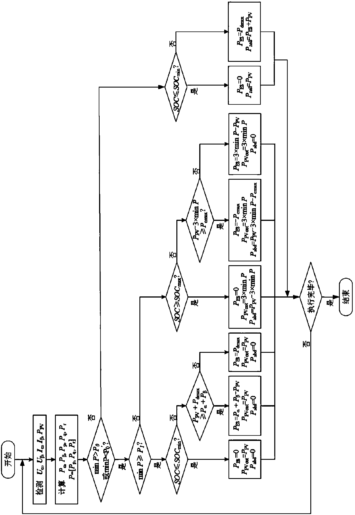
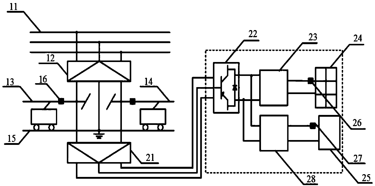

Image

  • Electrified railway three-phase photovoltaic DC side energy storage system and control method thereof
  • Electrified railway three-phase photovoltaic DC side energy storage system and control method thereof
  • Electrified railway three-phase photovoltaic DC side energy storage system and control method thereof

Examples


Embodiment Construction

[0041] In order to make the purpose, technical solution and advantages of the present invention clearer, the present invention will be further elaborated below in conjunction with the accompanying drawings.

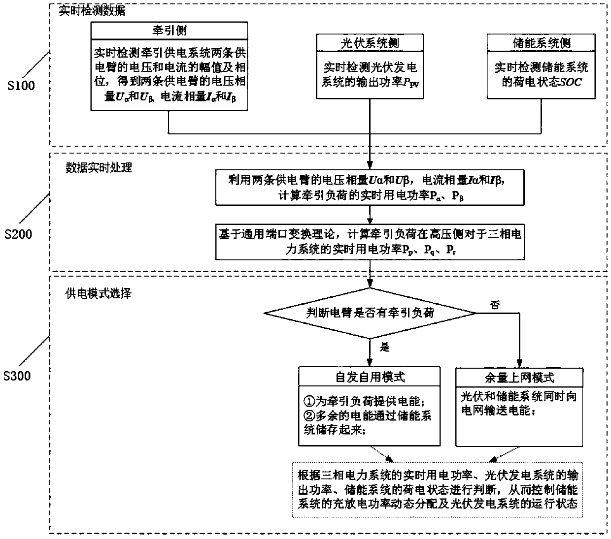
[0042] In this example, see figure 1 As shown, the present invention proposes a control method of a three-phase photovoltaic DC side energy storage system for an electrified railway. The three-phase photovoltaic DC side energy storage system for an electrified railway includes a traction power supply system, a photovoltaic power generation system, an energy storage system and a power system. The photovoltaic power generation system and the energy storage system are connected to a traction power supply system, and the traction power supply system is connected to an electric power system;

[0043] The control method includes the steps of:

[0044] S100, real-time detection data: real-time detection of the voltage phasor U of the two power supply arms on the traction side i...


PUM


Abstract

The present invention discloses an electrified railway three-phase photovoltaic DC side energy storage system and a control method thereof. A three-phase access mode is used by a photovoltaic power generation system, and an energy storage device is connected to a photovoltaic direct-current side. The operating mode selection is carried out according to real-time detection data and a processing result, and combined with traction load characteristics, a strategy of self-generation and use and extra power for grid is used. When a traction load is detected, a self-generation and use mode is used,when the power is supplied to the load, extra electric energy is stored in energy storage equipment, and an effect of 'peak-load shifting' is achieved. When an electric arm idle load is detected, themode is switched to an extra power for grid mode, and photovoltaic and energy storage equipment transmits electric energy to a grid at the same time. The reasonable dissipation of photovoltaic energycan be realized, a discarded electric quantity is reduced, at the same time, a configured energy storage capacity is reduced, and the economic efficiency of the system is improved.

Description

technical field [0001] The invention belongs to the technical field of electrified railways, and in particular relates to a three-phase photovoltaic DC side energy storage system for electrified railways and a control method thereof. Background technique [0002] With the rapid development of my country's electrified railways, as of the end of 2016, my country's railway operating mileage reached 124,000 kilometers, of which high-speed railways reached 22,000 kilometers. By 2020, my country's railway network will reach 150,000 kilometers, including 30,000 kilometers of high-speed railways, covering more than 80% of large cities. As a large industrial user of the power system, the railway system can consume up to 40 billion kWh of electricity annually, of which more than 50% is mainly consumed in the traction power supply system. In order to realize the energy saving and consumption reduction of electrified railways, the railway system itself is also actively promoting the de...

Claims


Application Information

Patent Timeline
Patent Type & Authority Applications(China)
IPC IPC(8): H02J3/00H02J3/38H02J3/28
CPCH02J3/383H02J3/00H02J3/28H02J2203/20Y02E70/30Y02E10/56
Inventor 戴朝华邓文丽邬明亮陈维荣时方力薛聪聪韩春白雪刘正杰
Owner SOUTHWEST JIAOTONG UNIV
Learn More