System And Method For Continuous Wave Constant Amplitude On-Resonance And Off-Resonance Spin-Lock For Magnetic Resonance Imaging

A technology of magnetic resonance imaging and spin lock, which is applied in the directions of using nuclear magnetic resonance imaging system for measurement, magnetic resonance measurement, and magnetic variable measurement, etc. It can solve problems such as image artifacts, reduce the application of image diagnostics, and spin lock failure

Active Publication Date: 2018-02-09
THE CHINESE UNIVERSITY OF HONG KONG
View PDF6 Cites 2 Cited by
  • Summary
  • Abstract
  • Description
  • Claims
  • Application Information

AI Technical Summary

Problems solved by technology

[0006] A challenge of T1ρ imaging and other spin-lock-based imaging methods is that spatial inhomogeneities in the B1RF and / or B0 fields may cause spin-lock failure in certain regions, leading to image artifacts such as banding
This reduces the diagnostic utility of the image

Method used


Image

  • System And Method For Continuous Wave Constant Amplitude On-Resonance And Off-Resonance Spin-Lock For Magnetic Resonance Imaging
  • System And Method For Continuous Wave Constant Amplitude On-Resonance And Off-Resonance Spin-Lock For Magnetic Resonance Imaging
  • System And Method For Continuous Wave Constant Amplitude On-Resonance And Off-Resonance Spin-Lock For Magnetic Resonance Imaging

Examples


Embodiment approach

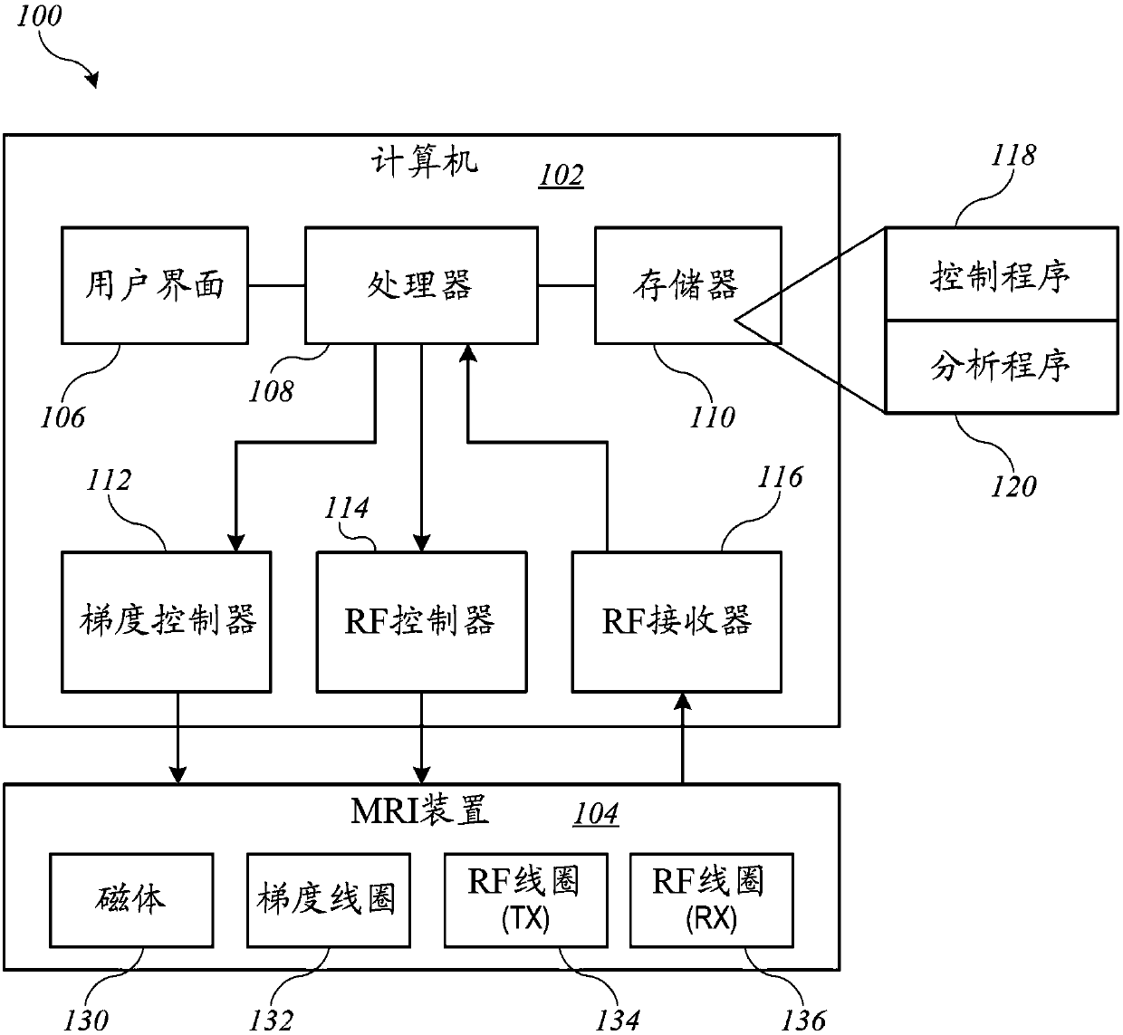
[0011] 1. A method of generating an image using a magnetic resonance imaging (MRI) apparatus, the method comprising:

[0012] Applying a magnetization preparation sequence consisting of an adiabatic half-channel (AHP), a constant-amplitude spin-lock RF pulse with a spin-lock time, and reverse AHP, where the RF amplitudes of the AHP and reverse AHP are equal to the spin lock amplitude;

[0013] implement a fetch sequence to fetch the dataset; and

[0014] Image data indicative of a spatial distribution of the spinlock-based imaging biomarkers for each of the plurality of locations in the region of interest of the individual is generated based on the acquired data set.

[0015] 2. The method of embodiment 1, wherein the spinlock-based imaging biomarker is T1p.

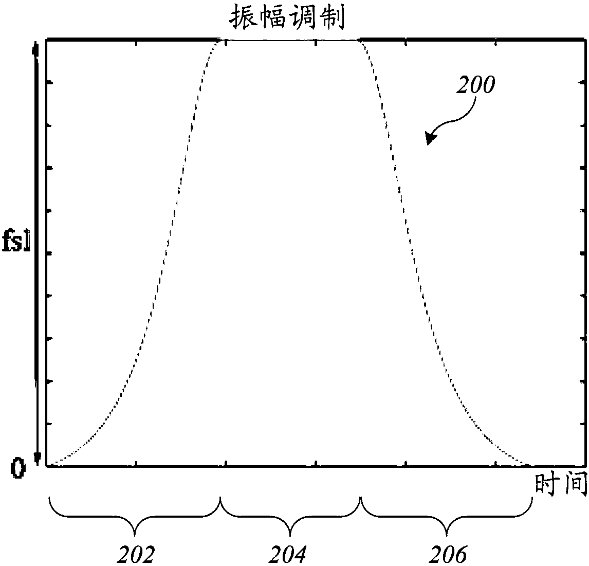
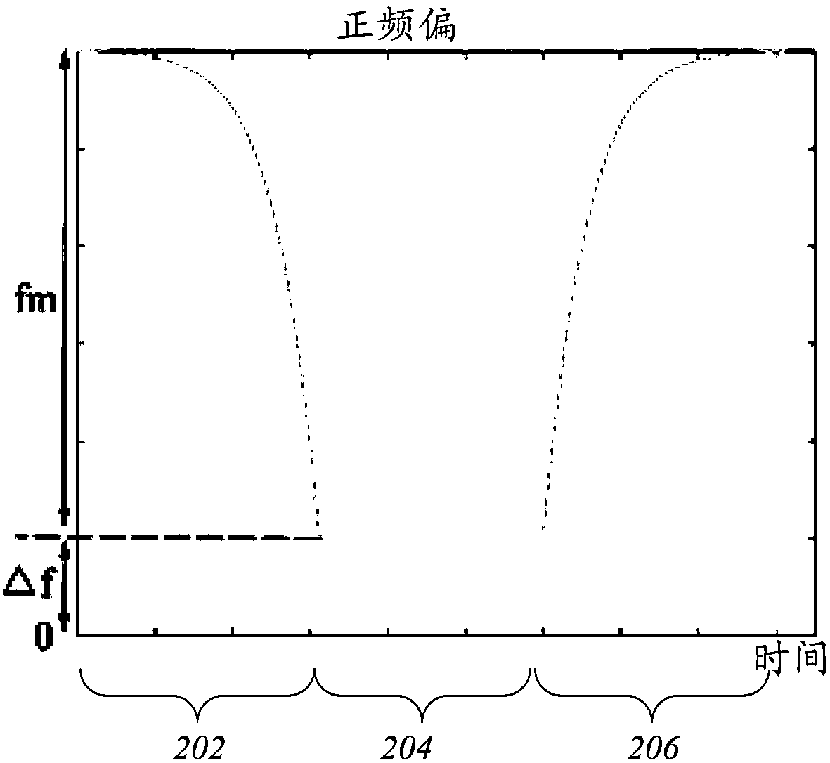
[0016] 3. The method of any one of embodiments 1 to 2, wherein the AHP has an amplitude modulation defined based on a hyperbolic secant function and a frequency modulation defined based on a hyperbolic tangent function...

Embodiment

[0232] Example: Simulation Study

[0233] To demonstrate the benefits of the techniques described herein, simulation studies were performed using full equation Bloch simulations. The signal is simulated as a function of TSL for different B0 and B1 field inhomogeneities. A simulation was performed for T1 = 900 ms, T2 = 35 ms, T1 p = 40 ms, T2 p = 70 ms and a spin-lock frequency of 500 Hz. Each of AHP and reverse AHP has a duration of 25ms, where A 0 =500Hz and β=4.

[0234] A simulation study demonstrates the effect of a dual acquisition approach. Figure 8A and 8B Three-dimensional stratigraphic plots of the measured error in T1p (vertical axis) as a function of actual T1p and T1 based on Bloch simulations are shown for different embodiments of the invention utilizing resonant spinlock generation. The initial magnetization prior to reverse AHP was generated using equation (13). The magnetization after reverse AHP was calculated based on the full Bloch equation simulation...


PUM


Abstract

MRI techniques provide robust imaging in the presence of inhomogeneity in the B1 (RF) and / or B0 magnetic fields. The techniques include using a magnetization prep sequence that includes an adiabatic half passage (AHP) followed by a spin-lock pulse, followed by a reverse AHP, after which a data acquisition sequence can be applied. The AHP and reverse AHP can have amplitude and frequency modulated to sweep through a region of frequency space. The RF amplitude of the AHP and reverse AHP can be designed to be equal to the spin-lock amplitude. Quantification of a magnetization relaxation parameter(e.g., T1rho) can use a modified relaxation model that accounts for relaxation effects during the reverse AHP. A dual-acquisition technique in which the reverse AHP of the second magnetization prep sequence has opposite frequency modulation to the reverse AHP of the first magnetization prep sequence can also be used.

Description

[0001] References to related applications [0002] This application claims priority to US Provisional Application No. 62 / 369,627, filed August 1, 2016, the disclosure of which is incorporated herein by reference in its entirety. Background of the invention [0003] The present application relates generally to Magnetic Resonance Imaging (MRI) techniques, and in particular to the technique of continuous wave constant amplitude generation of on-resonance and off-resonance spin locks, which can be effectively used in the presence of Cases of system imperfections, such as spatial inhomogeneities in the B1 radio frequency (RF) and B0 fields. For example, such techniques can be used to image and quantify T1p and other imaging biomarkers. [0004] Magnetic resonance imaging (MRI) is a non-invasive diagnostic technique that allows assessment of the composition and state of various tissues. During MRI, the patient is placed in a strong longitudinal magnetic field (B0), which aligns th...

Claims


Application Information

Patent Timeline
Patent Type & Authority Applications(China)
IPC IPC(8): A61B5/055
CPCA61B5/055A61B5/4244G01R33/56563G01R33/5659G01R33/50G01R33/446G01R33/5602G01R33/565
Inventor 陈蔚天江柏言
Owner THE CHINESE UNIVERSITY OF HONG KONG
Why Eureka
Try Eureka