Dry ice cleaning system and method applied to electronic module assembly process

An electronic module, dry ice cleaning technology, applied in cleaning methods and utensils, chemical instruments and methods, etc., can solve the problems of limited cleaning ability of ultrasonic cleaning process, inability to wash off metal powder, damage to module products, etc., and achieve convenient movement. Action, reduce floor space, reduce the effect of safety hazards

Active Publication Date: 2018-02-09
HUANWEI ELECTRONICS SHANGHAI CO LTD
View PDF5 Cites 1 Cited by
  • Summary
  • Abstract
  • Description
  • Claims
  • Application Information

AI Technical Summary

Problems solved by technology

However, in practical applications, the mechanical cleaning process will cause mechanical damage to the module product, secondary defects will occur, and fine dust will still remain on the module, which will affect the quality effect in the subsequent sputtering process
2. Water washing is a commonly used cleaning method in the industry. This method is simple and easy to implement and low in cost. However, as far as the cleaning process is concerned, water washing only has two aspects: impact peeling and dipping peeling
It has a very good effect in the cleaning of ordinary process dust. Similar to water washing, the cleaning ability of the ultrasonic cleaning process is limited, and the molten metal powder after laser cannot be washed away.

Method used


Image

  • Dry ice cleaning system and method applied to electronic module assembly process
  • Dry ice cleaning system and method applied to electronic module assembly process
  • Dry ice cleaning system and method applied to electronic module assembly process

Examples


Embodiment 1

[0090] Such as Figure 5 As shown, this embodiment discloses a dry ice cleaning system applied in the assembly process of electronic modules, including: an ice breaking mechanism 1000, a spray pipeline, a mechanical arm 1100, a cleaning base 1300 and a nozzle 1200. The nozzle 1200 is arranged towards the electronic module 8000 on the cleaning base 1300, and the view in this direction cannot show the specific structure of the nozzle 1200 installed on the mechanical arm 1100.

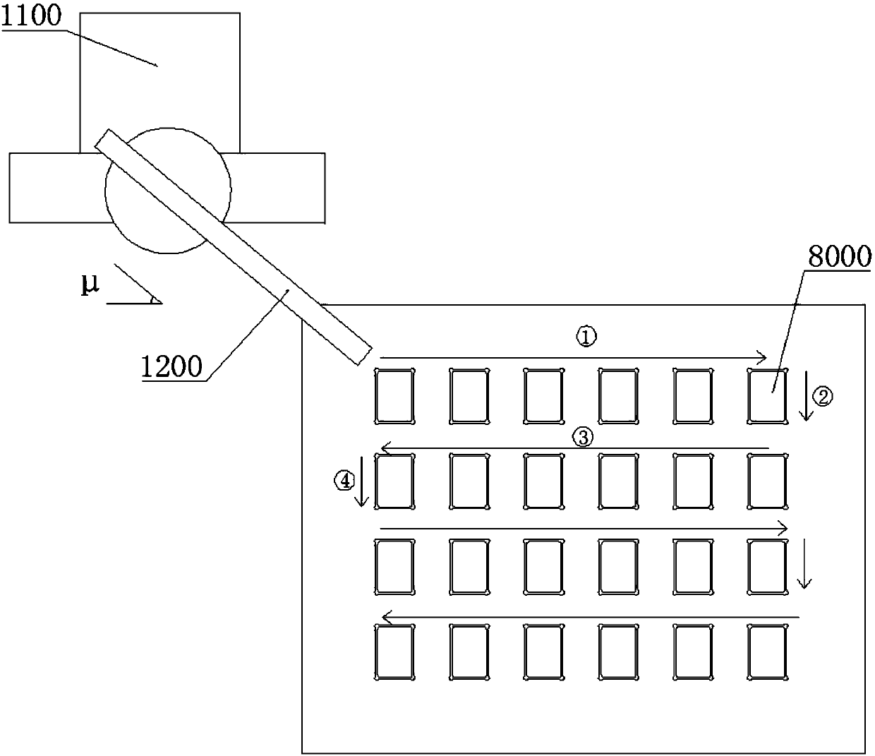
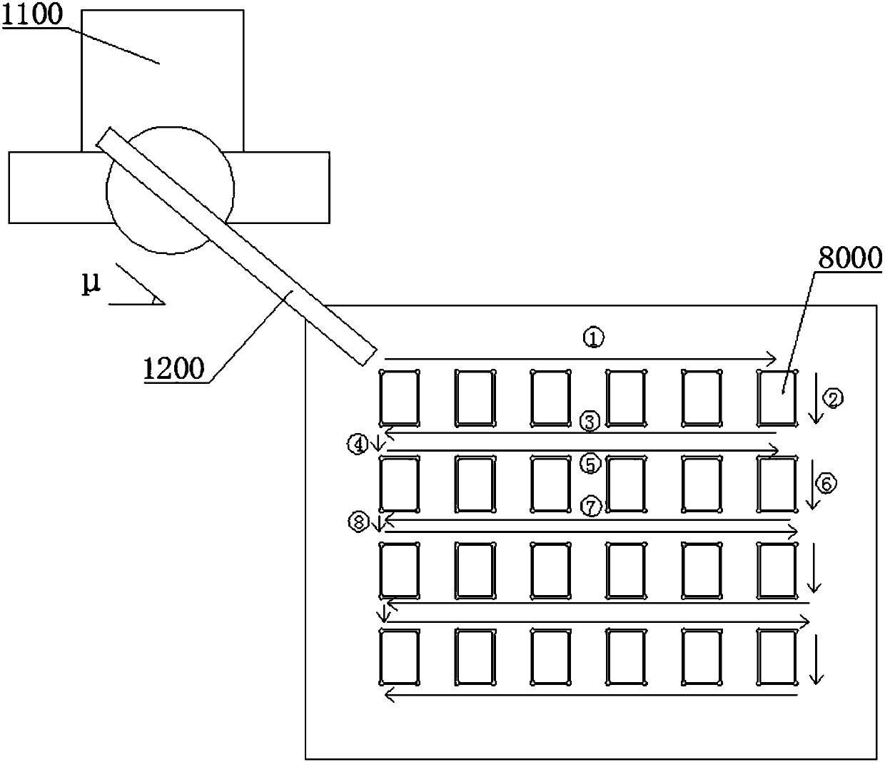
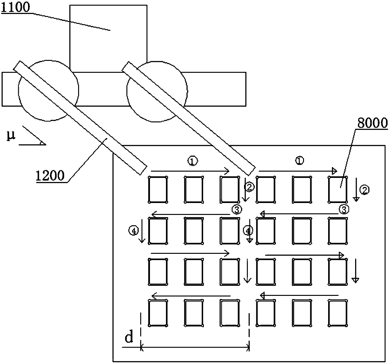
[0091] In order to better characterize the relative positional relationship between the nozzle and the electronic module, Figure 1-a , 1-b , 2-a, 2-b In four figures, the nozzle is rotated 90° to be parallel to the bottom surface of the cleaning base 1300 .

[0092] Such as Figure 1-a and Figure 1-b As shown, several electronic modules 8000 are arranged in a parallelogram array and fastened to the cleaning base 1300. Generally, the cross-sections of the electronic modules are polygonal shapes compose...

Embodiment 2

[0100] On the basis of Example 1, as Figure 6 , Figure 7 as well as Figure 8 As shown, the cleaning base 1300 is a box-shaped structure with an upper end face open, Figure 6 is the overall structure diagram of the box-like structure, Figure 7 Shown is a schematic cross-sectional structure diagram of the boxed structure, an annular gap 1350 is formed between the parallelogram array arranged by the electronic module 8000 and the side wall of the cleaning base 1300; the dry ice cleaning system of the electronic module also includes a dust filter ( not shown in the figure);

[0101] Such as Figure 6 As shown, the side wall of the cleaning base 1300 is provided with a first air hole 1360, a second air hole and a third air hole 1361, and the second air hole is located between the first air hole 1360 and the third air hole 1361, wherein the first air hole The second air hole faces the electronic module 8000, the first air hole 1360 and the third air hole 1361 face the annu...

Embodiment 3

[0103] On the basis of Example 2, such as image 3 As shown, the dry ice blasting system of the electronic module also includes a carrier 2000 for transferring the electronic module 8000; the parallelogram array on the carrier 2000 is arranged with mounting holes 2100 for the electronic module 8000, Figure 4 shows the detailed structure of the installation hole 2100, the installation hole 2100 includes a top-down platform section 2110 and a through-hole section 2120; wherein, the cross-sectional area of ​​the platform section 2110 is larger than the cross-sectional area of ​​the through-hole section 2120, and in A stepped surface 2111 is formed at the junction with the through hole section 2120 , and the electronic module 8000 is placed on the stepped surface 2111 . Generally, the outer contour of the pallet section 2110 is similar to that of the electronic module 8000 to limit it.

[0104] Such as Figure 7 , Figure 8 as well as Figure 9 As shown, the cleaning base 130...


PUM


Abstract

The invention discloses a dry ice cleaning system and method applied to the electronic module assembly process. The cleaning system comprises an ice breaking mechanism, an injection pipeline, a mechanical arm, a cleaning base and a nozzle. Multiple electronic modules are arranged in a parallelogram array manner and fastened to the cleaning base, and a heating structure for heating the electronic modules is arranged on the cleaning base. The ice breaking mechanism provides dry ice particles for the nozzle through the injection pipeline. The nozzle is arranged on the mechanical arm, and the nozzle is located above the cleaning base and can be aligned at the electronic modules for cleaning. The nozzle and the mechanical arm are rotationally connected so as to adjust the included angles between the nozzle and the surfaces of the electronic modules. The mechanical arm drives the nozzle to clean the surfaces and the sides of the electronic modules according to a snakelike reciprocating path.The advancing direction of the snakelike reciprocating path is parallel to the line direction of the parallelogram array. The snakelike reciprocating cleaning path is short in route, the speed is high, the dry ice cleaning system and method adapt to cleaning of the electronic modules in the parallelogram array form, and the automation degree is high.

Description

technical field [0001] The invention relates to the field of process equipment and methods in the assembly process of electronic products, in particular to a dry ice cleaning system and method used in the assembly process of electronic modules. Background technique [0002] For the production process of high-energy laser and other processing and cutting fields, more dust and foreign matter will be generated. The traditional cleaning processes in the industry include mechanical cleaning technology, reagent cleaning technology, and ultrasonic cleaning technology. Its practical application is relatively mature, but these methods have problems of varying degrees in practical application. [0003] 1. Mechanical cleaning technology is a relatively mature and perfect cleaning technology. It is mostly used in mold cleaning. It has the characteristics of simple and easy equipment and low requirements for cleaning tools. However, in practical applications, the mechanical cleaning pro...

Claims


Application Information

Patent Timeline
Patent Type & Authority Applications(China)
IPC IPC(8): B08B7/00B08B13/00
CPCB08B7/00B08B13/00
Inventor 卫丽冬黄文平谢松标黄林芸胡彪彭岩滨
Owner HUANWEI ELECTRONICS SHANGHAI CO LTD
Why Eureka
Try Eureka