
Special ultrasonic vibration auxiliary device for milling and application method thereof

An ultrasonic vibration and auxiliary device technology, applied in the field of milling, can solve problems such as unreasonable cutting parameters, large cutting force, and reduced tool service life, and achieve the effects of lowering temperature, reducing vibration lines, and reducing consumption.

Inactive Publication Date: 2018-02-09
SHENYANG AEROSPACE UNIVERSITY
View PDF4 Cites 10 Cited by
  • Summary
  • Abstract
  • Description
  • Claims
  • Application Information

AI Technical Summary

Problems solved by technology

[0005] However, the actual situation is that during the milling process, chatter marks often appear on the machined surface of the parts. The main reason for the chatter marks is that the cutting parameters are unreasonable, and the appearance of chatter marks also indicates that the processing quality of the part surface has declined. , as milling continues, the temperature of the cutting edge will become higher and higher, and the cutting force acting on the cutting edge will also increase, the direct consequence is to reduce the service life of the cutting tool

Method used


Image

  • Special ultrasonic vibration auxiliary device for milling and application method thereof
  • Special ultrasonic vibration auxiliary device for milling and application method thereof
  • Special ultrasonic vibration auxiliary device for milling and application method thereof

Examples


Embodiment Construction

[0027] The present invention will be further described in detail below in conjunction with the accompanying drawings and specific embodiments.

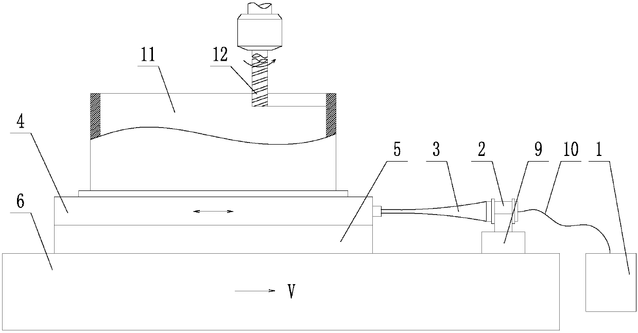
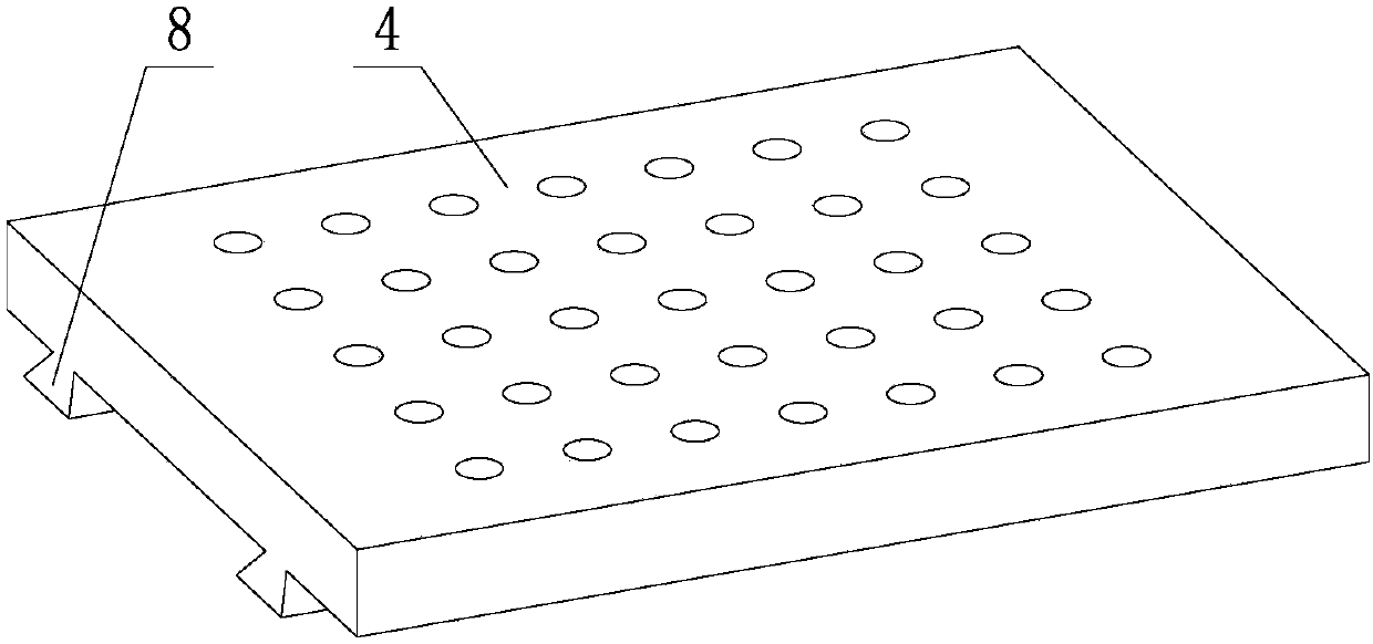
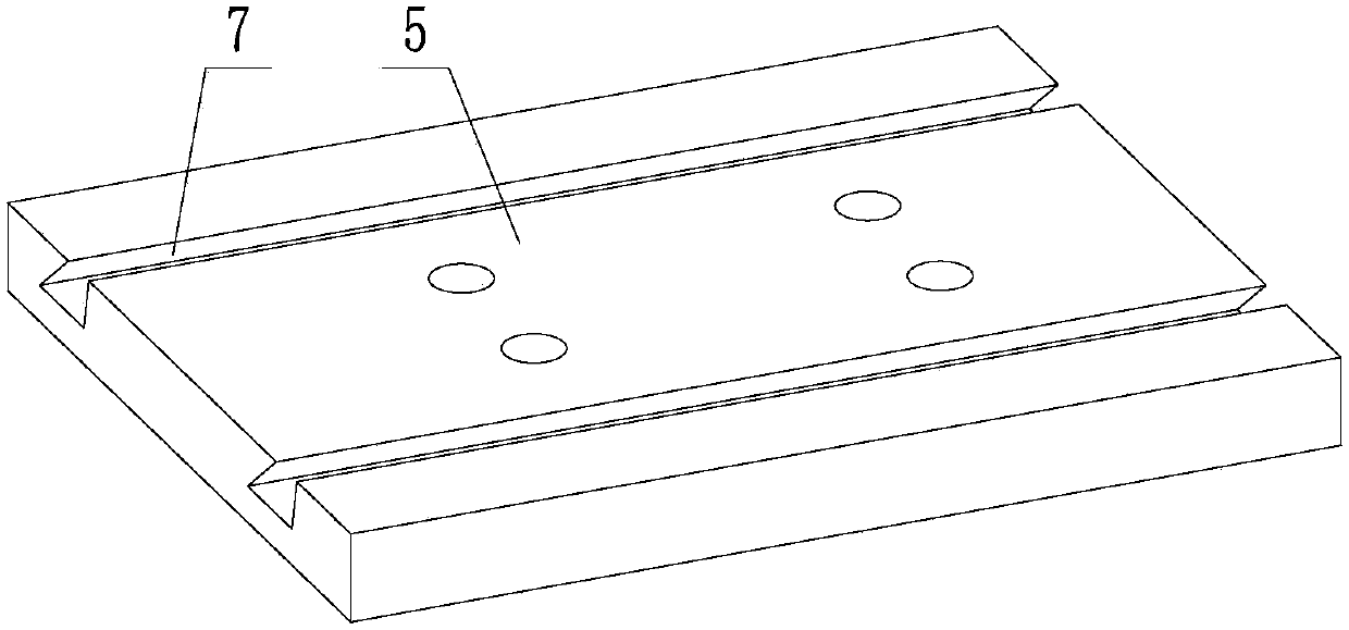
[0028] Such as Figure 1~3 As shown, a special ultrasonic vibration auxiliary device for milling includes an ultrasonic generator 1, a transducer 2, a horn 3, an ultrasonic vibration output plate 4 and an ultrasonic vibration guide plate 5; the ultrasonic vibration guide plate 5 is fixed by bolts Installed on the milling machine table 6, the upper surface of the ultrasonic vibration guide plate 5 is provided with a guide groove 7; the lower surface of the ultrasonic vibration output plate 4 is provided with a guide rail 8, and the ultrasonic vibration output plate 4 is located above the ultrasonic vibration guide plate 5, And the guide rail 8 is located in the guide groove 7, the ultrasonic vibration output plate 4 is slidingly matched with the ultrasonic vibration guide plate 5; the transducer 2 is fixedly installed on the milling ma...


PUM


Abstract

A special ultrasonic vibration auxiliary device for milling and its use method, the guide plate is fixed on the milling machine table, the guide plate is provided with a guide groove; the output plate is provided with a guide rail, the output plate is located above the guide plate, and the guide rail is located on the In the groove, the output plate and the guide plate are slidingly matched; the transducer is fixed on the milling machine table, and the horn is fixed horizontally between the transducer and the output plate; the ultrasonic generator is connected to the transducer through wires. The steps of the method of use are: respectively install the ultrasonic vibration guide plate, ultrasonic vibration output plate, transducer and parts on the milling machine table; connect the horn between the transducer and the ultrasonic vibration output plate; The device is connected to the ultrasonic generator; the milling tool is installed on the milling machine spindle; the milling machine and the ultrasonic generator are started; the ultrasonic vibration is output to the ultrasonic vibration output plate through the horn, and the parts are fed with the milling machine table; the parts are processed according to the milling parameters , turn off the milling machine and sonotrode, and remove the part.

Description

technical field [0001] The invention belongs to the technical field of milling, and in particular relates to a special ultrasonic vibration auxiliary device for milling and a method for using the same. Background technique [0002] At present, when machining parts by milling, the milling tools will inevitably be scrapped due to excessive wear. When the parts complete the milling process, a large amount of milling tools will usually be consumed, and the cost of milling tools as consumables will also be included in the cost of the parts. Among the processing costs, this also virtually increases the manufacturing cost of the parts. [0003] Many processing companies are trying to reduce the processing cost of parts, and the most urgent thing to reduce is the consumption of milling tools, so that parts can gain advantages in manufacturing costs, but the actual effect is not ideal. The consumption of milling tools Always high. [0004] In order to reduce the consumption of mill...

Claims


Application Information

Patent Timeline
Patent Type & Authority Applications(China)
IPC IPC(8): B23C3/00B23C9/00B06B1/02B06B3/02
CPCB23C3/00B06B1/02B06B3/02B23C9/00B23C2270/10
Inventor 王明海郑耀辉王奔李晓鹏
Owner SHENYANG AEROSPACE UNIVERSITY
Learn More