Supercharge Your Innovation With Domain-Expert AI Agents!

Plate automatic feeding device

A technology of automatic feeding and plate parts, applied in the direction of grinding/polishing safety device, grinding feed movement, grinding machine tool parts, etc., can solve the problem of affecting grinding quality and equipment accuracy, large consumption of sandpaper, and production efficiency Low-level problems, to achieve the effect of uniform consumption of sandpaper, low renovation cost, and improved service life

Pending Publication Date: 2018-02-09
GUANGDONG YIHUA TIMBER IND
View PDF6 Cites 10 Cited by
  • Summary
  • Abstract
  • Description
  • Claims
  • Application Information

AI Technical Summary

Problems solved by technology

[0008] The present invention proposes an automatic plate feeding device, which aims to solve the problems of high labor intensity, low production efficiency, large consumption of sandpaper, affecting grinding quality and equipment precision, etc. Uniform and fast feeding

Method used


Image

  • Plate automatic feeding device
  • Plate automatic feeding device
  • Plate automatic feeding device

Examples


Embodiment Construction

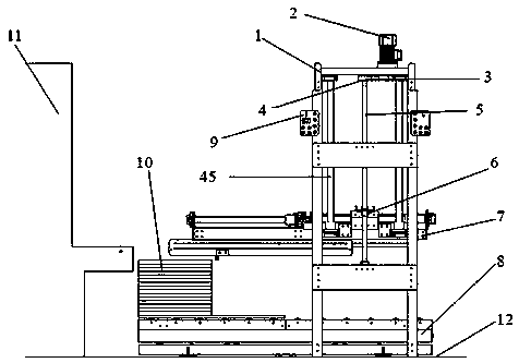
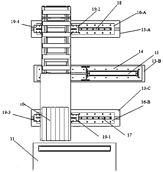
[0025] The automatic board feeding device has a structure including a frame 1, a lifting drive unit of the pushing mechanism, a pushing mechanism unit 7, a lifting and swinging mechanism of the plate; wherein, the lifting driving unit of the pushing mechanism includes a lifting motor 2 and a timing belt 3 , synchronous wheel 4, screw mandrel 5; lifting motor 2 is at the top of frame 1, the motor shaft of lifting motor 2 is connected with synchronous wheel 4 through synchronous belt 3, synchronous wheel 4 is at the upper end of screw mandrel 5, and screw mandrel 5 is vertical It is directly fixed on the side of the frame 1, the screw mandrel 5 is connected with the pushing mechanism unit 7 through the screw nut 6, and the plate lifting and swing mechanism is at the bottom of the frame 1.

[0026] Each of the four corners of the frame 1 has a column, and each column is fixed with a linear guide rail 45. The linear guide rail 45 is used as a lifting guide optical axis that limits ...


PUM


Abstract

The invention provides a plate automatic feeding device structurally comprising a rack, a pushing mechanism lifting driving unit, a pushing mechanism unit and a plate lifting and swinging mechanism. The pushing mechanism lifting driving unit comprises a lifting motor, a synchronous belt, a synchronous wheel and a lead screw, the lifting motor is located at the top of the rack, and a motor shaft ofthe lifting motor is connected with the synchronous wheel through the synchronous belt. The synchronous wheel is located at the upper end of the lead screw, the lead screw is vertically fixed to theside face of the rack, the lead screw is connected with the pushing mechanism unit through a nut, and the plate lifting and swinging mechanism is located at the bottom of the rack. The plate automaticfeeding device has the advantages that (1) the transformation cost is low; (2) the labor intensity of workers is relieved; (3) the production efficiency is improved; and (4) the product quality is improved, and the service life of a sanding machine is prolonged.

Description

technical field [0001] The invention relates to an automatic plate feeding device, which belongs to the technical field of automatic production. Background technique [0002] According to the characteristics of the existing flat sand machines in the market, the entrance width of the flat sand machines is generally about 1300mm, which is suitable for grinding widths from more than ten millimeters to several hundred millimeters, and the length is suitable for all woods greater than about 350mm; the existing plate lift-push The feeding machine is only suitable for plates with a large surface area. When changing to a flat sand machine with a large difference in width and length and feeding multiple pieces each time, it cannot solve the requirement of uniform use of sandpaper in the feeding process and the large change in length and size. The material requirements of sand flat wood; the diversity of shapes of furniture production materials and the anisotropy of wood itself determ...

Claims


Application Information

Patent Timeline
Patent Type & Authority Applications(China)
IPC IPC(8): B24B41/00B24B55/00
CPCB24B41/005B24B55/00
Inventor 刘壮超彭文明张圣清张宇鹏柯娇娜谢文昌
Owner GUANGDONG YIHUA TIMBER IND
Features
  • R&D
  • Intellectual Property
  • Life Sciences
  • Materials
  • Tech Scout
  • Unparalleled Data Quality
  • Higher Quality Content
  • 60% Fewer Hallucinations
Learn More