Cutting device for stone angle grinder

A cutting device and angle grinder technology, applied in abrasives, metal processing equipment, manufacturing tools, etc., can solve the problems of easy deformation, slow ash discharge, high cost, improve wear resistance and cutting sharpness, reduce distortion The effect of deformation and production cost reduction

Inactive Publication Date: 2018-02-09
QIDONG TIANSHAN TOOLS CO LTD
View PDF1 Cites 0 Cited by
  • Summary
  • Abstract
  • Description
  • Claims
  • Application Information

AI Technical Summary

Problems solved by technology

[0002] At present, the commercially available ultra-thin cutting blades are mainly used to cut some non-metallic objects that are relatively easy to cut. For some metal objects, the cutting blades will generate high heat during high-speed cutting. The internal distribution of the cutting disc causes excessive heat inside the ultra-thin cutting disc, so that the ultra-thin cutting disc is prone to distortion and deformation under the influence of these accumulated heat, and when the cutting disc is distorted and deformed, the size of the cutting disc itself is also It will change accordingly, resulting in a reduction in the machining accuracy and reliability of the cutting disc. In addition, during the cutting process of the workpiece, the friction surface of the workpiece and the cutting disc will continuously generate cutting heat. Under the influence of thermal expansion and cold contraction, it is easy to deform, so that the cutting teeth of the cutting wheel are easy to get stuck in the workpiece, reducing the stability of the cutting work of the cutting wheel
[0003] In view of the above phenomenon, the patent CN204149045U discloses a cutting piece, including a cutting body, the cutting body is a disc-shaped disc body, and a plurality of cutting blades are evenly distributed on the outer peripheral surface of the cutting body, and the adjacent There is a radially extending chute between the cutting blades, the bottom of the chute is a chip removal groove recessed from the outside to the inside, and the outer surface of the cutting blade and the outer surface of the chip removal groove are arranged with Superabrasive layer, the central position of the cutting body is provided with a mounting hole, and a plurality of cooling holes are evenly distributed along the periphery of the mounting hole. Curved from inside to outside in the counterclockwise direction, each heat dissipation hole is bent in the same direction from the inside to the outside in the circumferential direction of the cutting body, and the aperture size of the heat dissipation hole gradually increases along the counterclockwise direction of the cutting body; the cutting piece of this structure It can achieve stable cutting, increase the internal and external heat of the cutting disc, and reduce the amount of distortion; however, when the cutting disc with this structure is used for stone cutting, there are certain defects: 1. When used for stone cutting, there are more debris and dust discharge The speed is slow, which in turn causes the cutting efficiency of the stone cutting machine to be low; 2. Since the superhard film wear-resistant layer on the existing cutting blade is only a single-layer design, such as a copper layer, although its wear resistance has been increased, it cannot guarantee cutting The cutting sharpness of the cutting machine; such as the cobalt-nickel alloy layer, which not only ensures the degree of wear resistance, but also ensures the cutting sharpness of the cutting machine, but its cost is relatively high

Method used


Image

  • Cutting device for stone angle grinder
  • Cutting device for stone angle grinder

Examples


Embodiment

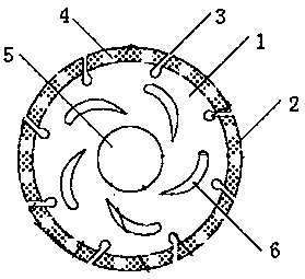
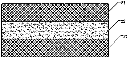
[0017] The present embodiment stone angle grinder is used cutting device, as figure 1 As shown, a disc cutting body 1 is included, and a plurality of cutting blades 2 are evenly distributed on the outer circumferential surface of the cutting body 1; between adjacent cutting blades 2, there are inclined grooves 3 extending in the radial direction, and the inclined grooves 3 The bottom of the cutting body is a chip removal groove A that is depressed from the outside to the inside, and the chute 3 is inclined clockwise from the inside to the outside in the radial direction of the cutting body. The outer surface of the cutting blade 2 is arranged with a superhard abrasive layer, and the superhard abrasive layer is a cobalt-nickel alloy layer 21, a copper layer 22 and a cobalt-nickel alloy layer 23 arranged in sequence from the inside to the outside; the superhard abrasive layer of each cutting blade 2 There are several chip removal grooves 4 extending radially along the disc cutti...


PUM


Abstract

The invention relates to a cutting device for a stone angle grinder, comprising a disc cutting body, a plurality of cutting blades are evenly distributed on the outer peripheral surface of the cutting body; The bottom of the chute is a chip removal groove A that is depressed from the outside to the inside, and the outer surface of the cutting blade is arranged with a superhard abrasive layer, and the superhard abrasive layer is a cobalt-nickel alloy layer and a copper layer arranged in sequence from the inside to the outside. and a cobalt-nickel alloy layer, the superabrasive layer of each cutting edge is provided with several chip removal grooves B extending radially along the disc cutting body, thereby forming several fine superabrasive layers; the center of the cutting body A mounting hole is opened at the position, and a plurality of cooling holes are evenly distributed along the periphery of the mounting hole. The cooling holes are arc-shaped, and the cooling holes are curved in a counterclockwise direction from the inside to the outside in the circumferential direction of the cutting body. The advantages of the present invention are: the cutting device for the stone angle grinder of the present invention can increase the ash discharge speed and improve the cutting efficiency; it can also improve the wear resistance and cutting sharpness and reduce the production cost.

Description

technical field [0001] The invention belongs to the technical field of cutting tools, in particular to a cutting piece for a stone angle grinder. Background technique [0002] At present, the commercially available ultra-thin cutting blades are mainly used to cut some non-metallic objects that are relatively easy to cut. For some metal objects, the cutting blades will generate high heat during high-speed cutting. The internal distribution of the cutting disc causes excessive heat inside the ultra-thin cutting disc, so that the ultra-thin cutting disc is prone to distortion and deformation under the influence of these accumulated heat, and when the cutting disc is distorted and deformed, the size of the cutting disc itself is also It will change accordingly, resulting in a reduction in the machining accuracy and reliability of the cutting disc. In addition, during the cutting process of the workpiece, the friction surface of the workpiece and the cutting disc will continuousl...

Claims


Application Information

Patent Timeline
Patent Type & Authority Applications(China)
IPC IPC(8): B24D5/12B24D5/10
CPCB24D5/12B24D5/10
Inventor 戴帅东
Owner QIDONG TIANSHAN TOOLS CO LTD
Why Eureka
Try Eureka