Planar joint robot

A technology of planar joints and robots, which is applied in the direction of manipulators, program-controlled manipulators, manufacturing tools, etc., can solve the problems of increased load mass and inertia, slow response, affecting the accuracy and stability of the end, and achieves stable vertical operation, Improves motion and responsiveness, reduces size

Pending Publication Date: 2018-02-09
上海新时达机器人有限公司
View PDF0 Cites 5 Cited by
  • Summary
  • Abstract
  • Description
  • Claims
  • Application Information

AI Technical Summary

Problems solved by technology

[0006] The inventor finds that there are at least the following problems in the prior art: image 3 Although the structure of the robot shown reduces the size of the forearm of the robot and the moment of inertia when the forearm of the big arm rotates, the movement of the vertical direction of the end is changed to be performed by the connection between the base and the big arm, resulting in the vertical direction of the end of the robot The forearm and forearm need to be driven during movement, so that the mass and inertia of the driven load greatly increase when running vertically, requiring a larger power actuator and slowing down the response, and when the forearm and forearm are longer The movement of the cantilever structure in the vertical direction will easily cause the shaking of the forearm or even the whole machine, seriously affecting the accuracy and stability of the end

Method used


Image

  • Planar joint robot
  • Planar joint robot
  • Planar joint robot

Examples


Embodiment Construction

[0028] In order to make the purpose, technical solutions and advantages of the embodiments of the present invention more clear, various implementation modes of the present invention will be described in detail below in conjunction with the accompanying drawings. However, those of ordinary skill in the art can understand that, in each implementation manner of the present invention, many technical details are provided for readers to better understand the present application. However, even without these technical details and various changes and modifications based on the following implementation modes, the technical solution claimed in this application can also be realized.

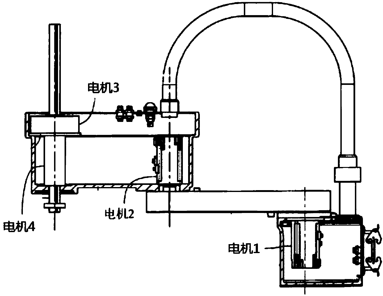
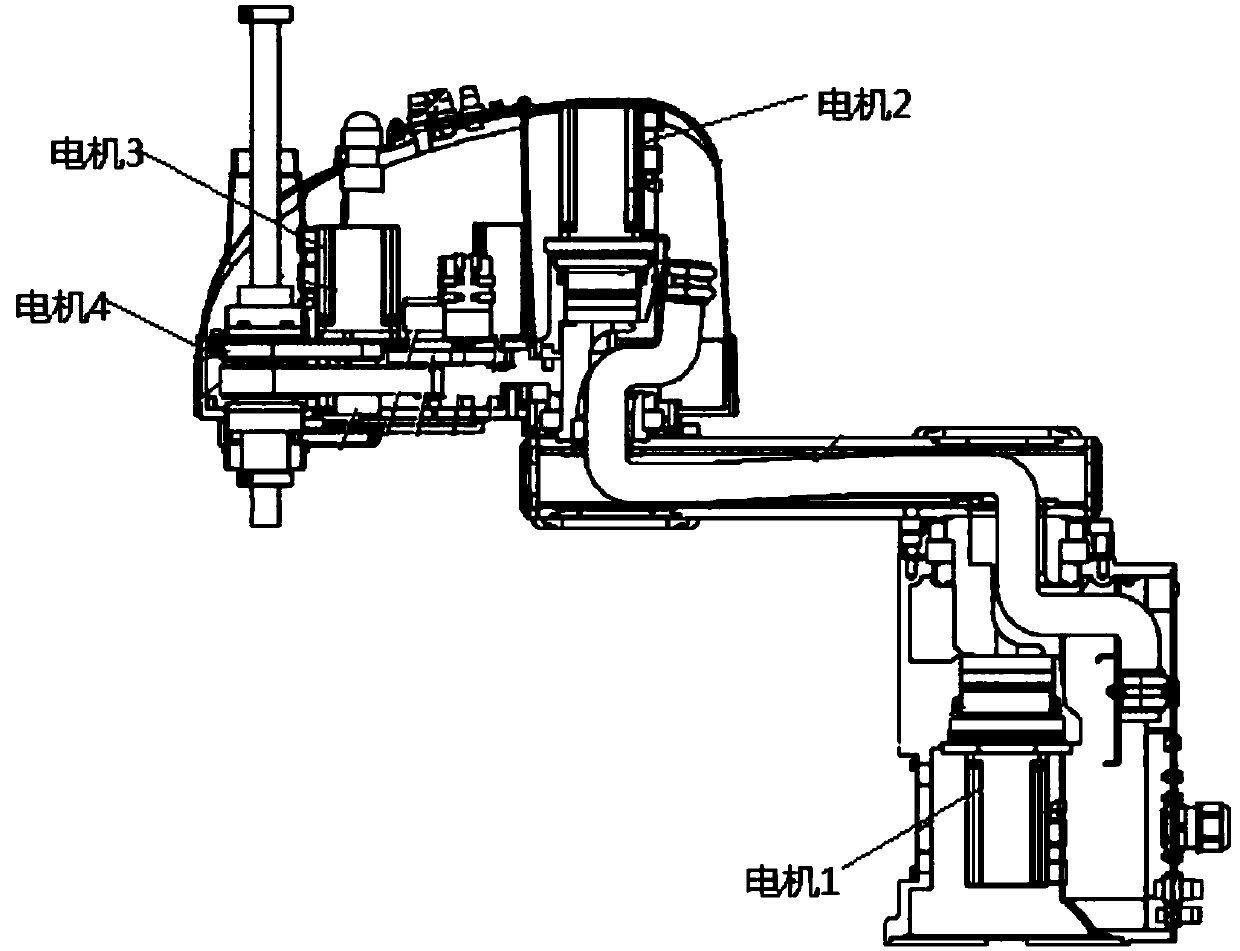
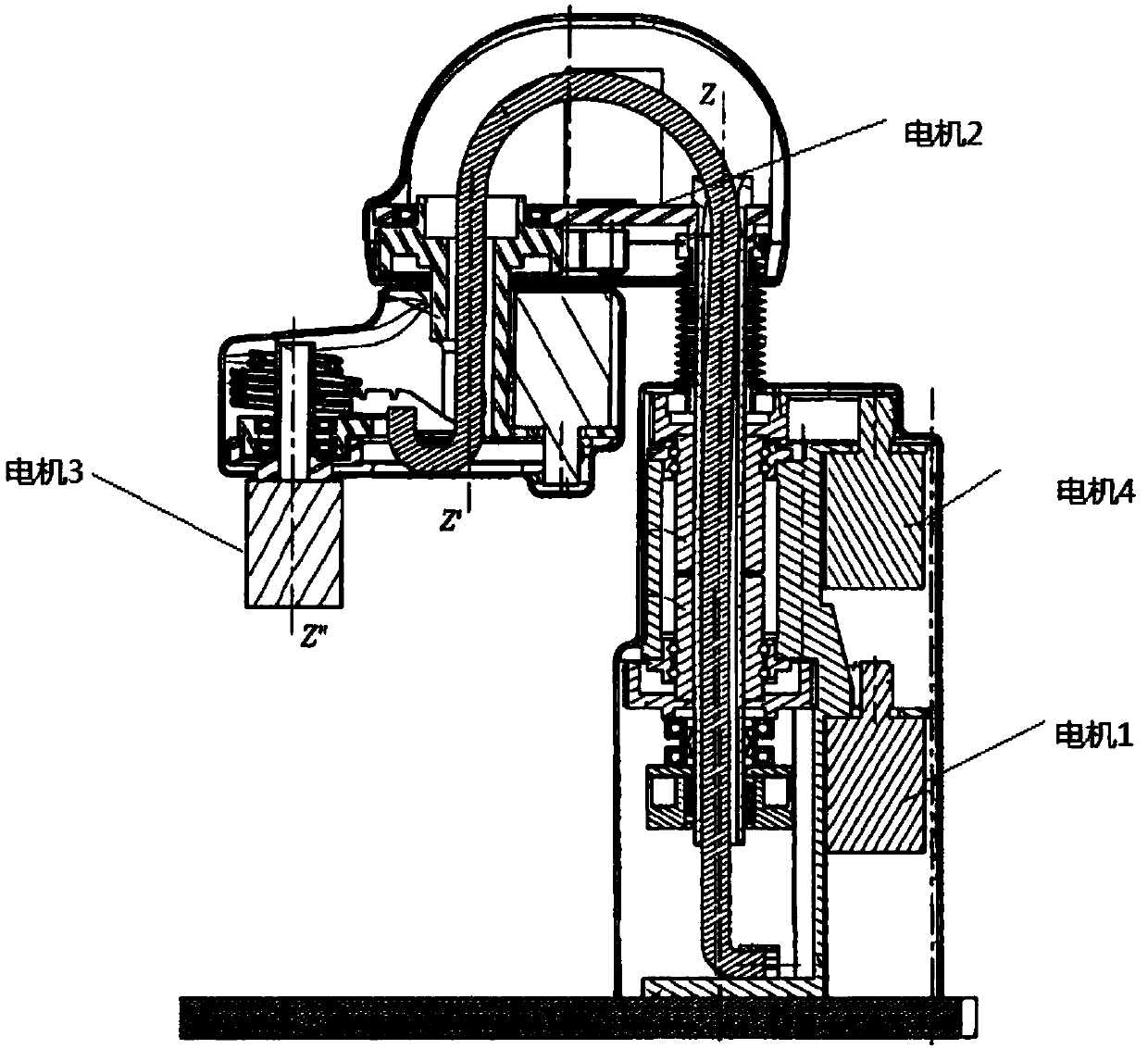
[0029] A first embodiment of the present invention relates to a planar joint robot. Such as Figure 4 Shown is a perspective view of the planar joint robot in this embodiment, which is composed of a base 10 , a large arm 11 , a forearm 12 and a tool end 13 .

[0030] Wherein, the base 10 is a base with a c...


PUM


Abstract

The embodiment of the present invention relates to the industrial field, and discloses a planar joint robot. In the present invention, a planar joint robot is provided, comprising: a base with a concave structure, a boom connected to the base in the cavity of the base, and an arm connected to the end of the boom outside the cavity of the base The forearm and the tool end arranged at the end of the forearm; wherein, a first motor for controlling the horizontal rotation of the large arm and a second motor for controlling the horizontal rotation of the forearm are arranged in the base, and a motor for controlling the horizontal rotation of the tool end is arranged in the large arm The third motor is provided with a fourth motor for controlling the vertical movement of the tool end in the forearm. By placing a part of the motor in the forearm of the planar robot at the rear, the size and motion inertia of the forearm are reduced, and only the tool end at the end of the forearm is required to be driven during vertical movement, without the need for vertical movement of both the large arm and the forearm. Responsiveness of movement and stability while performing operations.

Description

technical field [0001] The embodiments of the present invention relate to the industrial field, in particular to a planar joint robot. Background technique [0002] Industrial robots integrate advanced manufacturing technologies such as precision, flexibility, intelligence, and software application development. By implementing detection, control, optimization, scheduling, management, and decision-making on the process, they can increase production, improve quality, reduce costs, and reduce Resource consumption and environmental pollution are the highest manifestations of industrial automation. The currently widely used planar joint robot (Selective Compliance Assembly Robot Arm, SCARA) is a multi-axis robot suitable for working on a horizontal plane. Typically a SCARA robot includes a fixed axis, such as a base fixed to a tabletop. The robot is also provided with a boom movable about a fixed axis, usually a vertical axis of rotation. In addition, the robot is also equippe...

Claims


Application Information

Patent Timeline
Patent Type & Authority Applications(China)
IPC IPC(8): B25J9/00B25J9/04B25J9/10B25J9/12B25J19/00
CPCB25J9/0009B25J9/04B25J9/104B25J9/126B25J19/00
Inventor 李晓华王师石德宇张敏梁焦瑶
Owner 上海新时达机器人有限公司
Why Eureka
Try Eureka