Upper limb powered exoskeleton mechanism system

A mechanism system and exoskeleton technology, applied in the field of robotics, can solve the problems of low system structural rigidity, low motion stability, poor dynamic balance, etc., and achieve the effects of enhancing system rigidity and stability, fast response speed, and low cost.

Pending Publication Date: 2018-02-09
UNIV OF ELECTRONIC SCI & TECH OF CHINA
View PDF0 Cites 17 Cited by
  • Summary
  • Abstract
  • Description
  • Claims
  • Application Information

AI Technical Summary

Problems solved by technology

The electric drive system has a simple structure and high precision, but it is heavy and has poor dynamic balance; hydraulically driven power-assisted exoskeleton robots have strong load-bearing capacity and high ri

Method used


Image

  • Upper limb powered exoskeleton mechanism system
  • Upper limb powered exoskeleton mechanism system
  • Upper limb powered exoskeleton mechanism system

Examples


Example Embodiment

[0032] Example one:

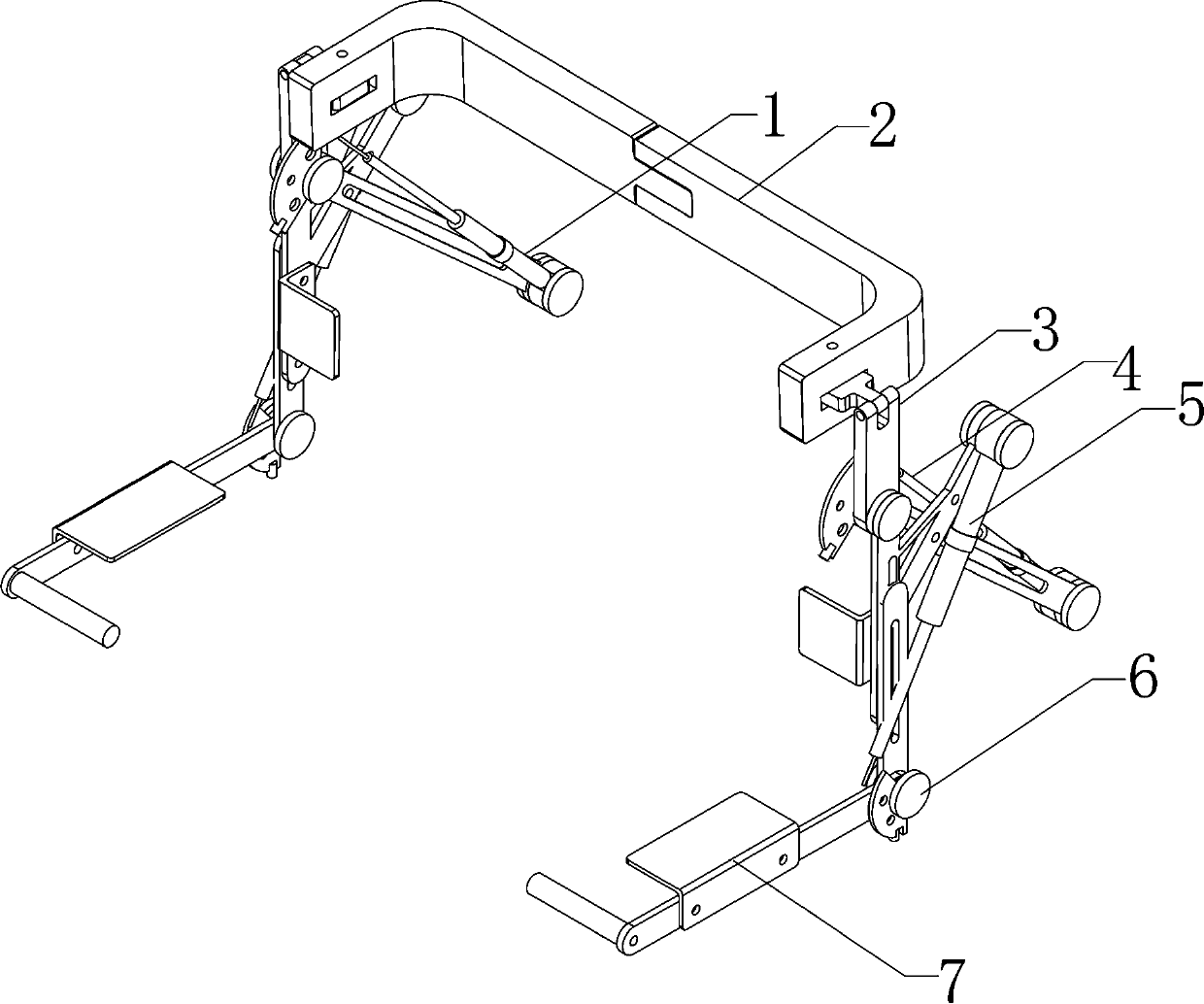
[0033] In the active assist mode, the system predicts the movement trend of the upper limbs according to the feedback data of the surface electromechanical instrument worn by the human body. The upper limb assisted exoskeleton mechanism calculates the elongation of each gas-liquid cylinder and controls it to achieve the prediction through the posture calculation. Position, so that the power-assisted exoskeleton mechanism reaches the predetermined position in advance, realizing active power assistance.

[0034] The working process of the implementation plan:

[0035] By detecting the contact force signal between the operator and the exoskeleton, when the force of the contact point reaches a certain preset threshold, the exoskeleton is controlled to follow the human body movement in time, thereby reducing the load on the operator and guiding the patient or The bearer carries out active physical rehabilitation training and assistance work.

Example Embodiment

[0036] Embodiment two:

[0037] In the passive assist mode, the upper limb assisted operator is generally a rehabilitation patient with no athletic ability. In this mode, the upper limb assisted exoskeleton mechanism system forms a predetermined upper limb movement pattern through a pre-programmed motion posture plan, and the operator accepts it as a passive The person moves accordingly.

[0038] The working process of the implementation plan:

[0039] According to the limb movement needs of rehabilitation patients, through programming, the movement planning route is programmed into the control system of the upper limb assisted exoskeleton mechanism. By reading the system’s shoulder and elbow joint sensor information, the angle data of each joint is read in real time. Pose inverse calculation and closed-loop control strategy to complete passive assistance.

[0040] In summary, the patent of the present invention uses a gas-liquid tandem cylinder structure to replace the traditional p...


PUM


Abstract

The invention provides an upper limb powered exoskeleton driving system. The upper limb powered exoskeleton driving system is composed of an upper arm gas and liquid driving cylinder, a strap, shoulder inner side joints, shoulder front stretching joints, a lower arm gas and liquid driving cylinder, elbow joints and a lower arm supporting frame. According to the upper limb powered exoskeleton driving system, the gas and liquid series connection cylinders serve as a driving executor of the shoulder joints and the elbow joints in an upper limb powered exoskeleton mechanism, on the basis that fastness of an original pneumatic system is retained, the rigidity and stability of the system are enhanced by means of a hydraulic portion, the defects that the pneumatic system is poor in stability, lowin structural rigidity and the like are overcome, and meanwhile the compliant capacity and the running precision of the system are improved. Compared with pneumatic, electric and hydraulic systems, the upper limb powered exoskeleton mechanism system has the beneficial effects of being high in power-to-mass ratio and power-to-volume ratio, high in responding speed, low in cost, clean, free of pollution and the like, the compliance of exoskeletons can be improved, and the total weight of the system is reduced.

Description

Technical field [0001] The invention relates to the technical field of robots, in particular to an upper limb assisted exoskeleton mechanism system in the field of exoskeleton assisted robots. Background technique [0002] The upper limb booster exoskeleton is a wearable human-machine integrated intelligent booster device, which is widely used in military, industrial and human rehabilitation training fields. Therefore, the development and application of this kind of power-assisted exoskeleton robot has very practical significance. [0003] The power-assisted exoskeleton began in 1960, the individual power-assisted exoskeleton Hardiman developed by the American GE company. This system is used to enhance the soldier's arm holding capacity. In 2000, the US Defense Prospective Research Project Agency (DARPA) launched the "Enhanced Human Function (EHPA)" research program, pushing exoskeleton research to a climax. Subsequently, the University of Berkeley in Canada, Raytheon Corporation...

Claims


Application Information

Patent Timeline
IPC IPC(8): B25J9/00B25J9/14
CPCB25J9/0006B25J9/14
Inventor 王洪艳陆金波刘萌
Owner UNIV OF ELECTRONIC SCI & TECH OF CHINA
Why Eureka
Try Eureka