A liquid incubator
A technology of liquid strains and incubators, which is applied in the field of bioengineering and can solve the problems of easy pollution of liquid strain incubators
- Summary
- Abstract
- Description
- Claims
- Application Information
AI Technical Summary
Problems solved by technology
Method used
Image
Examples
Embodiment 1
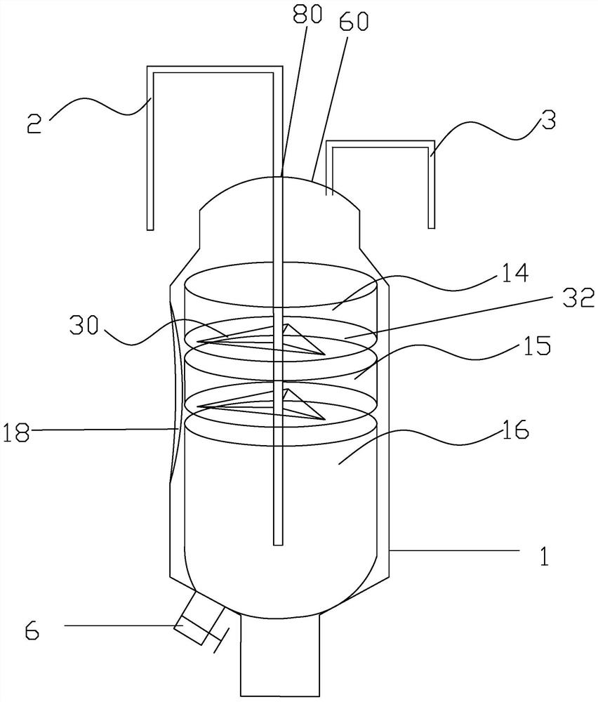
[0039]A liquid incubator, such as figure 1 As shown, it is mainly composed of the outer tank body 1, the cover 60 positioned at the top of the outer tank body 1, and the first inner tank 16 for holding the liquid culture medium arranged inside the outer tank body 1 in sequence from bottom to top. The second inner tank 15 and the third inner tank 14 that put the solid culture medium are composed, and the incubator also includes an air inlet pipeline 2 and an exhaust pipeline 3 that extend into the inside of the incubator through a cover 60, and the air inlet pipeline 2 passes through the second inner tank. Three inner tanks 14, the second inner tank 15 extend into the bottom of the first inner tank 16, the bottom of the outer tank body 1 is provided with a discharge port 6, and the side wall of the outer tank body 1 is provided with an observation mirror 18, the first inner tank body The upper ends of the tank 16 and the second inner tank 15 are open structures, and the bottom ...
Embodiment 2
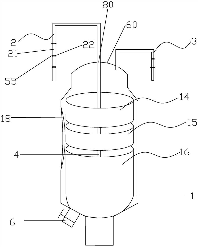
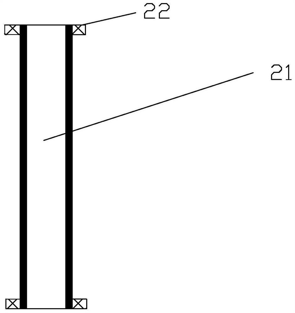
[0041] The difference between the liquid incubator provided by Embodiment 2 of the present invention and Embodiment 1 is that, as figure 2 , image 3 and Figure 4 As shown, the end of the air inlet pipeline 2 and the exhaust pipeline 3 away from the incubator is connected with a filter assembly, the filter assembly includes a filter membrane 55 and a fixed assembly located on the upper and lower sides of the filter membrane 55, and the fixed assembly includes a ventilation pipe 21 and the connectors 22 fitted on the outer surfaces of the two ends of the ventilation pipe 21 are located on both sides of the filter membrane 55 and are detachably connected by bolts or threads between the adjacent connectors 22, which play a better role in the filter membrane 55. Fixed function, at the same time, the filter membrane 55 can be replaced according to the actual situation, which is more convenient and reliable. The present invention can filter air more flexibly by using the filter a...
Embodiment 3
[0043] The difference between the liquid incubator provided by Embodiment 3 of the present invention and Embodiment 2 is that the material opening is an equilateral triangle, such as Figure 5 As shown, the movable cover plate assembly 30 includes n cover plates 31 arranged symmetrically along the central point of the material opening, the cover plates 31 are hinged to the side of the bottom plate 32 corresponding to the material opening, and when the three cover plates 31 are closed , the gaps between adjacent cover plates 31 are distributed, and a closed plate cover 90 is formed, and the center of the closed plate cover 90 is provided with a through hole 33 for the air intake pipeline 2 to pass through, such as Figure 6 As shown, the cover plate 31 is hinged to the side of the bottom plate 32 corresponding to the material opening through the hinge 91, the hinge 91 is located at the lower end of the side of the bottom plate 32, and the upper end of the side of the bottom plat...
PUM
 Abstract
Description
Claims
Application Information
 - R&D
- Intellectual Property
- Life Sciences
- Materials
- Tech Scout
- Unparalleled Data Quality
- Higher Quality Content
- 60% Fewer Hallucinations
Browse by: Latest US Patents, China's latest patents, Technical Efficacy Thesaurus, Application Domain, Technology Topic, Popular Technical Reports.
© 2025 PatSnap. All rights reserved.Legal|Privacy policy|Modern Slavery Act Transparency Statement|Sitemap|About US| Contact US: help@patsnap.com


