
Gantry tank immersion type production line overturning jig structure

A production line and tank immersion technology, applied in the direction of cells, electrolysis process, electrolysis components, etc., can solve problems such as workpiece defects, blind hole air cannot be completely exhausted, and working fluid corrodes workpieces, etc.

Pending Publication Date: 2018-02-09
ZHEJIANG ASIA PACIFIC MECHANICAL & ELECTRONICS
View PDF8 Cites 0 Cited by
  • Summary
  • Abstract
  • Description
  • Claims
  • Application Information

AI Technical Summary

Problems solved by technology

[0002] At present, many workpieces have blind holes. When electroplating equipment is used to electroplate workpieces with blind holes, in the process of bath immersion chemical treatment, if the blind holes are downward, the workpiece is placed in the working solution At this time, the air in the blind hole cannot be completely exhausted, and the air bubbles will accumulate on the upper side of the blind hole, causing the working fluid to be unable to fully contact the part where the air bubbles accumulate in the blind hole, resulting in no coating / plating, rust, color difference, etc. ; If the blind hole is upward, when the workpiece is taken out from the working fluid, the working fluid in the blind hole cannot flow out, and the residual liquid will remain in the blind hole, causing the reaction time between the blind hole and the working fluid to be too long, causing the working fluid to corrode the workpiece, At the same time, the working fluid will be brought into the next process to affect the next process, resulting in workpiece defects

Method used


Image

  • Gantry tank immersion type production line overturning jig structure
  • Gantry tank immersion type production line overturning jig structure
  • Gantry tank immersion type production line overturning jig structure

Examples


Embodiment 1

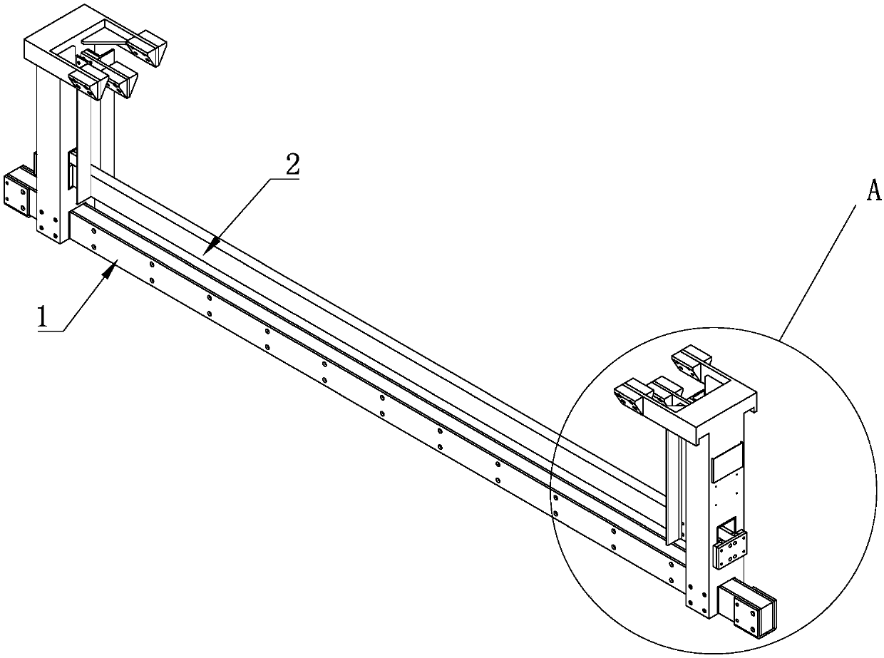
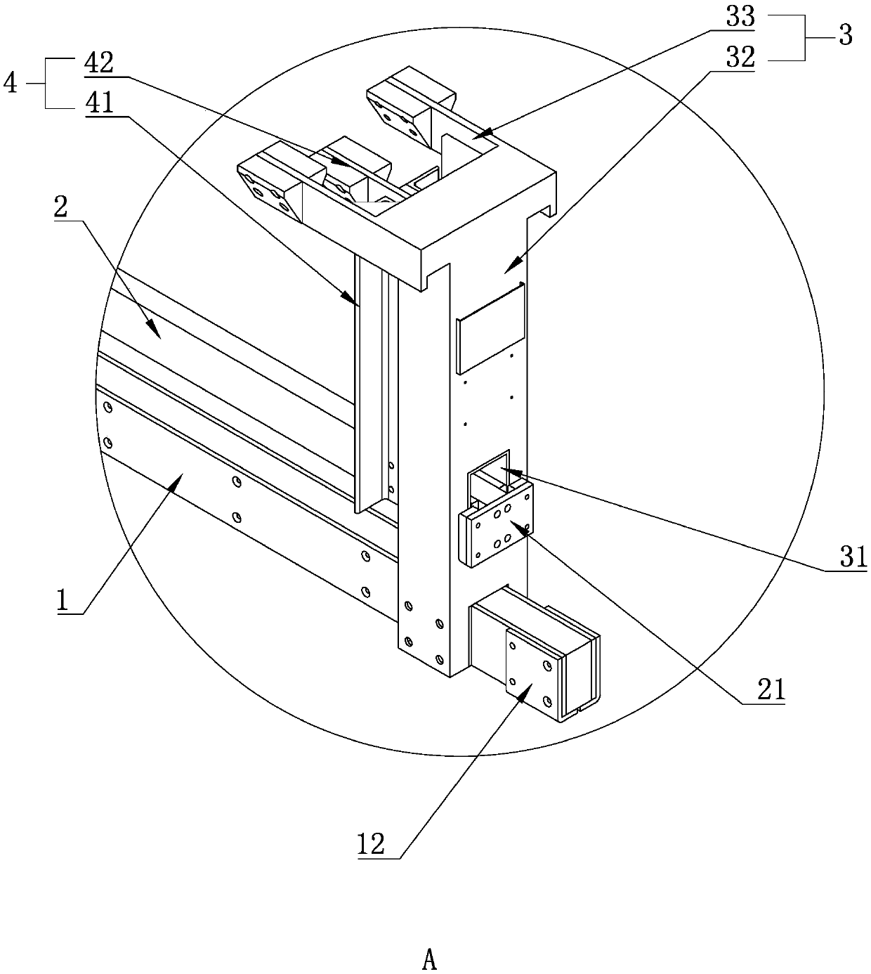
[0034] A flip hanger structure for a gantry tank-immersed production line, including a driving frame and a flying bus arranged on the driving frame. The flying bus includes a main bus 1 and an auxiliary bus 2 connected to both ends of the main bus 1 to drive the main bus 1 The main bar lifting rod 3 moving in the vertical direction and the auxiliary bar lifting rod 4 connected to the two ends of the auxiliary bar 2 to drive the auxiliary bar 2 to move in the vertical direction. The auxiliary bar limit groove 31 for the horizontal displacement of the bar lifting rod 3, the auxiliary bar limit groove 31 is matched with the end of the auxiliary bar 2, the auxiliary bar limit groove 31 runs through the main bar lifting bar 3, and the auxiliary bar 2 The two ends of the auxiliary bar pass through the limit groove 31 of the auxiliary bar respectively, and the two ends of the auxiliary bar 2 are provided with the limit block 21 that is offset against the outer wall of the main bar lif...

Embodiment 2

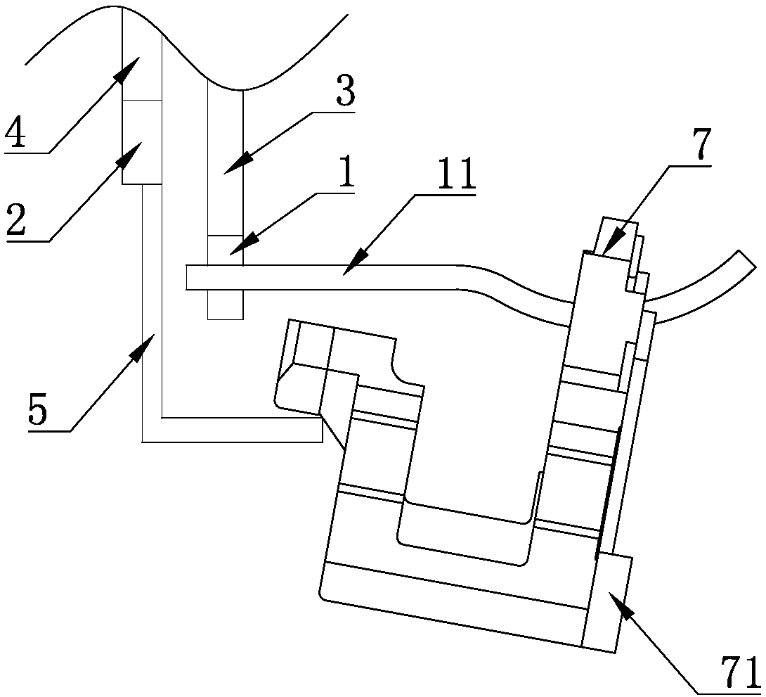
[0040] The difference between this embodiment and the first embodiment is that the turning component is a turning lever 61 that is rotatably connected to the auxiliary bus 2. The turning lever 61 is in an inverted "L" shape and is located above the product 7. There is a limit piece 62 which can be against the top of the turning lever 61 to make the turning lever 61 rotate.

[0041] When the driving lifting hook is lowered, the height of the side of the flip bar 61 close to the auxiliary bus 2 is lowered, so that the flip bar 61 presses down the side of the top of the product 7, so that the product 7 rotates around the hook 11, so that the hook 11 is hung on the hook. The blind hole 71 of the product 7 faces obliquely upward; when the lifting hook of the vehicle is lowered, the height of the side of the turning bar 61 close to the auxiliary bus 2 is raised, and the limit member 62 limits the top of the turning bar 61, so that the turning bar 61 Rotate clockwise around the stopp...


PUM


Abstract

The invention discloses a gantry tank immersion type production line overturning jig structure. The gantry tank immersion type production line overturning jig structure comprises a crane frame and a fly bar arranged on the crane frame. The fly bar comprises a main bar, a secondary bar, main bar lifting rods connected with the two ends of the main bar to drive the main bar to move in the vertical direction, and secondary bar lifting rods connected with the two ends of the secondary bar to drive the secondary bar to move in the vertical direction. The main bar lifting rods are provided with secondary bar limiting grooves used for preventing the secondary bar from moving relative to the main bar lifting rods in the horizontal direction, and the secondary bar limiting grooves are matched withthe ends of the secondary bar. The main bar is provided with a hook for hanging a product. The secondary bar is provided with an overturning assembly for pushing the product to turn up and down aroundthe hook. Through the relative movement between the secondary bar and the main bar when the fly bar is immersed in work liquid and taken away from the work liquid, the secondary bar drives the overturning assembly to overturn the product hung on the main bar, and uncoating / non-plating, rusting, color differences and other phenomena of a blind hole in the product caused by bubbles or accumulatingliquid are prevented.

Description

technical field [0001] The invention belongs to the field of electroplating equipment, and in particular relates to a flip hanger structure for a gantry tank dipping production line. Background technique [0002] At present, many workpieces have blind holes. When electroplating equipment is used to electroplate workpieces with blind holes, in the process of bath immersion chemical treatment, if the blind holes are downward, the workpiece is placed in the working solution At this time, the air in the blind hole cannot be completely exhausted, and the air bubbles will accumulate on the upper side of the blind hole, causing the working fluid to be unable to fully contact the part where the air bubbles accumulate in the blind hole, resulting in no coating / plating, rust, color difference, etc. ; If the blind hole is upward, when the workpiece is taken out from the working fluid, the working fluid in the blind hole cannot flow out, and the residual liquid will remain in the blind ...

Claims


Application Information

Patent Timeline
IPC IPC(8): C25D21/10C25D17/08
CPCC25D17/08C25D21/10Y02P70/50
Inventor 冯凯轶韩鉴波邹翔潘正权
Owner ZHEJIANG ASIA PACIFIC MECHANICAL & ELECTRONICS
Learn More