Bi-directional bulb through-flow turbine capable of achieving automatic switching

A technology of automatic conversion and bulb cross-flow, which is applied in the fields of two-way tubular water turbines and tidal power generation, can solve problems such as complex structures, and achieve the effect of small size, simple shape and stable operation

Inactive Publication Date: 2018-02-09
涪陵善通有限责任公司
View PDF6 Cites 9 Cited by
  • Summary
  • Abstract
  • Description
  • Claims
  • Application Information

AI Technical Summary

Problems solved by technology

This patent application ingeniously uses the sliding reversing of the water flow to realize that the water flow in both directions can keep

Method used


Image

  • Bi-directional bulb through-flow turbine capable of achieving automatic switching
  • Bi-directional bulb through-flow turbine capable of achieving automatic switching
  • Bi-directional bulb through-flow turbine capable of achieving automatic switching

Examples


Embodiment Construction

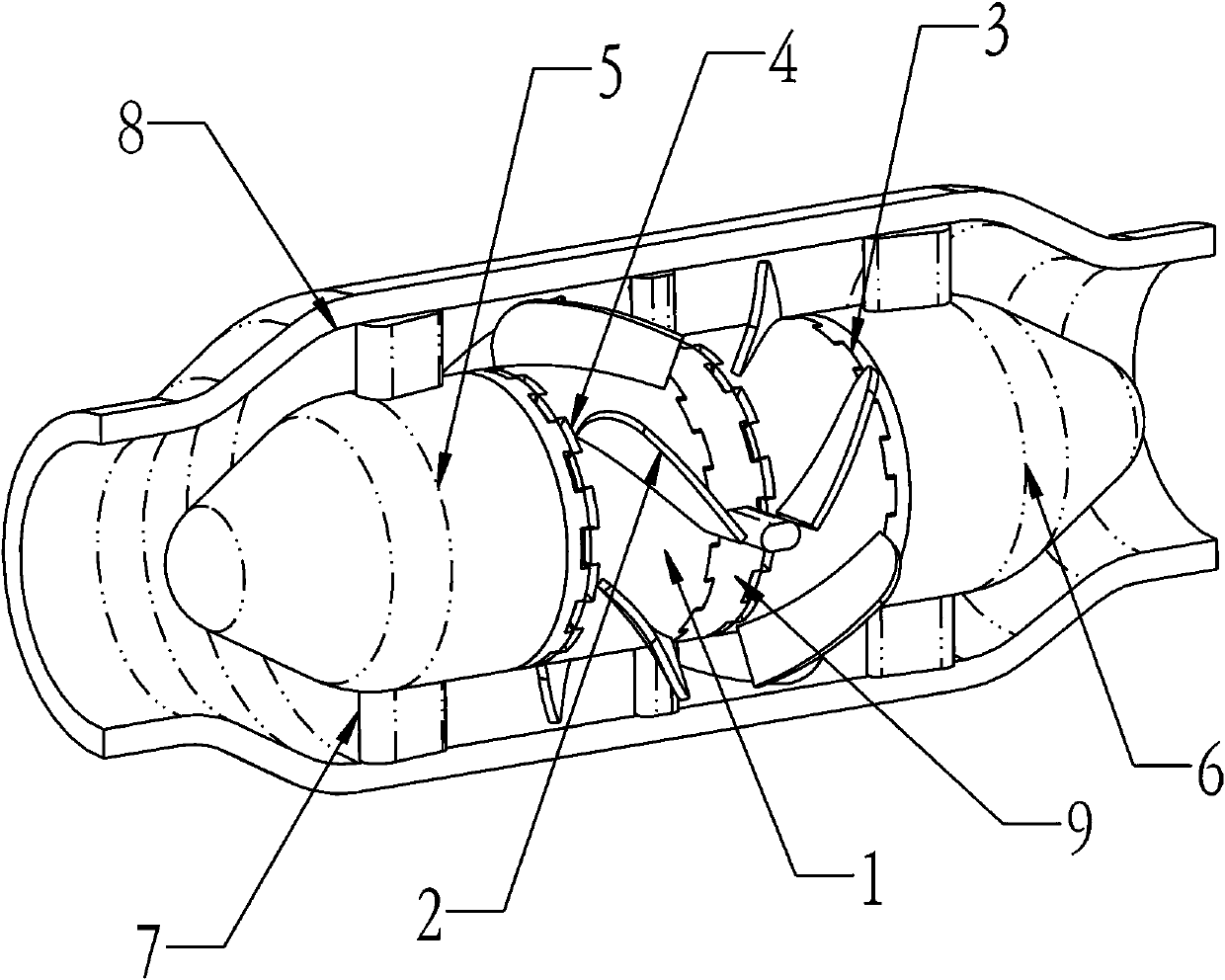
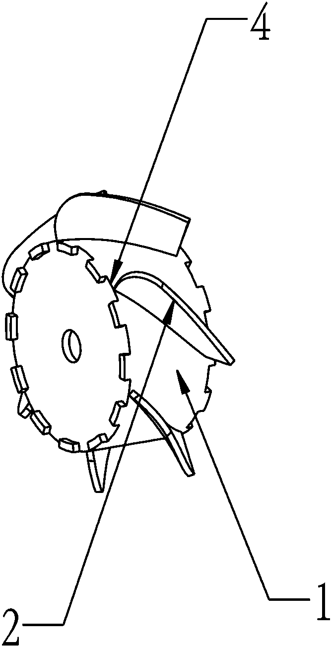
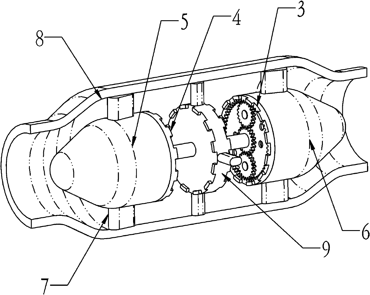
[0011] The guide vane and runner 1 can be automatically converted into a tubular water turbine. A main shaft protrudes from the tail of the bulb body 5, and other parts are sealed. The other end of the main shaft is connected to the bearing seat 6, and the outside of the bearing seat 6 is connected to the support 7. , the outside of the bulb body 5 is connected with the support 7, the outside of the fixed wheel 9 is connected with the support 7, and the support 7 is connected with the shell 8; a pair of right clutches 3 are arranged on the right side of the two runners 1, and a pair of left clutches 4 are arranged on the left side. The outer half of the clutch can rotate around the main shaft; there is a fixed wheel 9 in the middle, and half of the clutches that cannot rotate are arranged on both sides of the fixed wheel 9; there are two runners 1, and half of the clutches are arranged on both ends of the runner 1. There are helical blades 2 evenly distributed on the outer circ...


PUM


Abstract

The invention discloses a bi-directional bulb through-flow turbine capable of achieving automatic switching. A spindle stretches out of the tail of a bulb body, and other parts are sealed; the other end of the spindle is connected to a bearing seat, and the exterior of the bearing seat is connected with a support; the exterior of the bulb body is connected with the support, and the exterior of a fixed wheel is connected with the support; the support is connected with a shell; the right sides of two turning wheels are provided with a pair of right clutches, and the left sides of the two turningwheels are provided with a pair of left clutches; half of the clutches which are located on the two sides and close to the exterior can rotate around the spindle, and the fixed wheel is arranged in the middle; the two sides of the fixed wheel are each provided with half of the clutches which cannot rotate; the two turning wheels are arranged, and the two end surfaces of each turning wheel are each provided with half of the clutches; spiral blades are evenly distributed on the outer circles of the turning wheels around the axes, the right spiral blade is arranged on one turning wheel, and theleft spiral blade is arranged on the other turning wheel; circular holes matched with the spindle are formed in the middles of the turning wheels, and the turning wheels can rotate around the spindleand can slide around the axis of the spindle; and the end surfaces of the bearing seat and the bulb body are both provided with transmission mechanisms, and the clutches and a planetary gear train arearranged.

Description

technical field [0001] The invention relates to a tubular water turbine, in particular to an "automatically converted two-way bulb tubular water turbine", which belongs to fluid machinery and is a two-way tubular water turbine mainly used for tidal power generation. Background technique [0002] Chinese patent application number: 201010255892.1, "a two-way power generation device using tidal energy", also includes a sliding device, a water flow sliding plate, a water turbine shaft and a water wheel, and the gearbox includes a box body, a forward gear device, a reverse gear device and The water turbine gear, the forward gear device and the reverse gear device are all connected with the speed change device by the transmission input shaft, the water turbine gear is connected with the water turbine shaft, the generator input shaft, the transmission input shaft and the water turbine shaft are parallel, and the water flow slides The plate is connected with the water turbine gear b...

Claims


Application Information

Patent Timeline
IPC IPC(8): F03B3/04F03B3/12F03B11/00F03B13/26
CPCF03B3/04F03B3/126F03B11/00F03B13/26Y02E10/20Y02E10/30
Inventor 许可王敬姚晓光许昌义
Owner 涪陵善通有限责任公司
Why Eureka
Try Eureka