Hydraulic valve

A hydraulic valve and valve body technology, applied in the field of hydraulic valves, can solve the problems of affecting work efficiency, increasing the sliding resistance of the valve core, and reducing the transmission medium, achieving good flexibility and anti-corrosion performance, improving sealing effect, manufacturing low cost effect

Inactive Publication Date: 2018-02-09
WUHU ZHONGYI HYDRAULIC TECH
View PDF5 Cites 4 Cited by
  • Summary
  • Abstract
  • Description
  • Claims
  • Application Information

AI Technical Summary

Problems solved by technology

In the hydraulic system, the cleanliness of the medium directly affects the response speed of the control valve and the normal operation of the system. When the cleanliness of the transmission medium is high, there is no debris between the valve core and the valve body, and the valve core slides smoothly; When the cleanliness of the medium is low, the sliding resistance of the valve core in the valve body becomes larger, and the response speed of the valve becomes slower, thus affecting the working efficiency
As the dirt increases, the spool will be stuck and unable to slide
When there is less impurity gas in the transmission medium, it will be discharged through the hydraulic valve; when there is more impurity gas in the transmission medium, the transmission medium will be pushed to the outside of the valve body together with the impurity gas. The effect becomes worse
Traditional hydraulic valves are deficient in intelligent control, mostly manual control, unable to realize automatic control

Method used


Image

  • Hydraulic valve

Examples


specific Embodiment approach

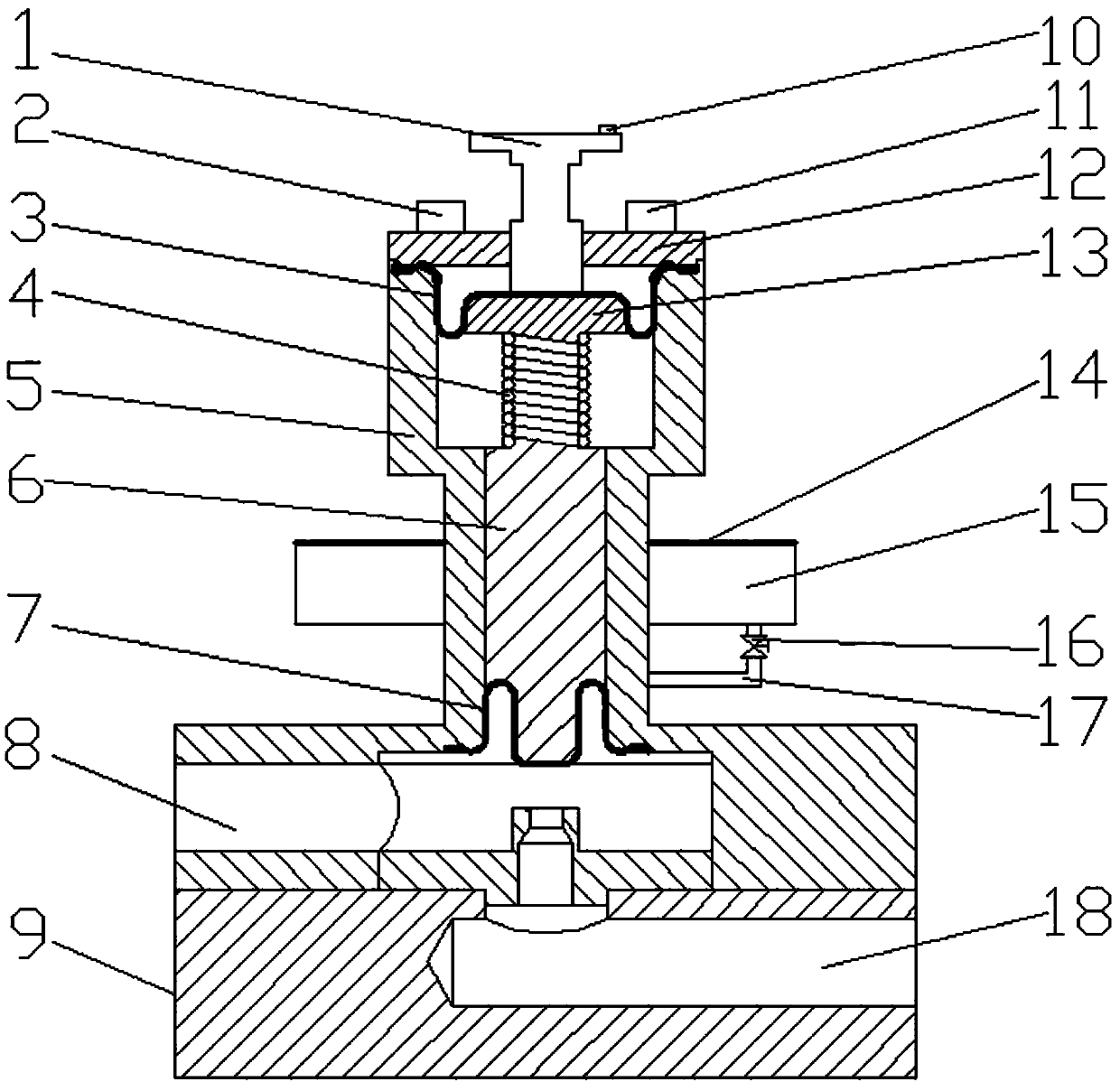
[0012] figure 1 A specific embodiment of the present invention is shown: a hydraulic valve, including a valve body 5, a valve core 6, a valve seat 9, a valve cover 12, a timer 2, a PLC controller 11, an operating handle 1, a spring valve seat 13, a power switch 10. Return spring 4, annular oil bearing groove 15, sealing cover 14, pipe 17, valve 16, upper diaphragm 3, lower diaphragm 7, upper oil port 8, lower oil port 18, valve body 5 is filled with sealing oil, valve seat 9 A valve core 6 is provided between the part extending into the valve body 5 and the hydraulic valve cover 12; The lower end of the valve body 5; the timer 2 is fixed on the left end of the valve cover 12; the PLC programmable controller 11 is fixed on the right end of the valve cover 12, and one end of the PLC programmable controller 11 is connected to the timer 2; the operating handle 1 is connected to the spring below Valve seat 13; power switch 10 is located at the right end of the upper surface of ope...


PUM


Abstract

The invention discloses a hydraulic valve. The hydraulic valve comprises a valve body, a valve core, a valve seat, a valve cover, a timer, a PLC controller, an operating handle, a spring valve seat, apower source switch, a reset spring, an annular oil bearing tank, a sealing cover, a pipeline, an upper membrane, a lower membrane, an upper oil port and a lower oil port. The valve core is arrangedbetween the part, extending into the valve body, of the valve seat and the hydraulic valve cover. The PLC programmable controller is fixedly arranged at the right end of the valve cover, and one end of the PLC programmable controller is connected with the timer. The annular oil bearing tank is fixedly arranged in the middle of the outer side of the valve body. The upper membrane is arranged at thetop of the spring valve seat, the lower membrane is arranged at the bottom of the valve core, and the upper oil port and the lower oil port communicate with a main channel cavity. The hydraulic valveis convenient to install and high in safety, and can achieve automation control. The upper membrane and the lower membrane can conduct isolation sealing on the inner cavity of the valve body and a driving component, and thus impurities in the outside world can be prevented from affecting cleanness of a medium. The PLC controller can effectively control the disconnection and connection time of thehydraulic valve according to the arranged timer, and thus the self-locking function of the hydraulic valve is achieved.

Description

technical field [0001] The invention relates to the hydraulic field, in particular to a hydraulic valve. Background technique [0002] The hydraulic valve is an automatic component operated by pressure oil. It is controlled by the pressure oil of the pressure distribution valve. It is usually used in combination with the electromagnetic pressure distribution valve. It can be used to remotely control the on-off of the oil, gas and water pipeline system of the hydropower station. In the hydraulic system, the cleanliness of the medium directly affects the response speed of the control valve and the normal operation of the system. When the cleanliness of the transmission medium is high, there is no debris between the valve core and the valve body, and the valve core slides smoothly; When the cleanliness of the medium is low, the sliding resistance of the valve core in the valve body becomes larger, and the response speed of the valve becomes slower, thus affecting the working ef...

Claims


Application Information

Patent Timeline
Patent Type & Authority Applications(China)
IPC IPC(8): F15B13/02F16K7/16
CPCF15B13/02F16K7/16
Inventor 蔡国定张平平何关清
Owner WUHU ZHONGYI HYDRAULIC TECH
Why Eureka
Try Eureka