Synergized heat supply device with CO2 air source heat pump

An air source heat pump and heating device technology, applied in the field of heat pumps, can solve the problems of centralized heating of radiators, the inability to realize the circulation heating method, and the high water outlet temperature of the heat pump cannot be used well, so as to increase the heat and increase the temperature of the water outlet Effect

Pending Publication Date: 2018-02-09
何铭
View PDF5 Cites 2 Cited by
  • Summary
  • Abstract
  • Description
  • Claims
  • Application Information

AI Technical Summary

Problems solved by technology

” Therefore, CO 2 The air source heat pump mainly adopts the heating method of primary heating, which can only be used in the hot water bathing project, and cannot realize the circulation heating method. 2 The high outlet water temperature of the heat pump will not be put to good use

Method used


Image

  • Synergized heat supply device with CO2 air source heat pump
  • Synergized heat supply device with CO2 air source heat pump

Examples


Embodiment Construction

[0016] The invention will be further described below in conjunction with the accompanying drawings and specific embodiments.

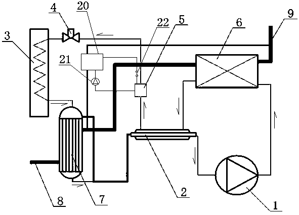
[0017] like figure 1 As shown, a CO 2 The air source heat pump synergistic heating device includes a first compressor 1, a regenerator 2, a gas cooler 6, an evaporator 3, a heat exchanger 5, a condenser 20, a second compressor 21 and an intermediate processor 7, the first A compressor 1 is connected to the gas inlet of the gas cooler 6, and the gas outlet of the gas cooler 6 is connected to the regenerator 2, and the regenerator 2 is respectively connected to the first compressor 1 and the heat exchanger 5, and the heat exchanger 5 They are respectively connected to the condenser 20 and the evaporator 3, the pipeline connecting the heat exchanger 5 and the evaporator 3 is provided with a first throttling valve 4, and the pipeline connecting the heat exchanger 5 and the condenser 20 is provided with a second throttling valve. The valve 22, the first t...


PUM


Abstract

The invention discloses a synergized heat supply device with a CO2 air source heat pump. The device mainly comprises a first compressor, a heat regenerator, a gas cooler, an evaporator, a heat exchanger, a condenser, a second compressor and a central processing unit. The heat exchanger, the condenser, the second compressor and a second throttle valve form a simple and easy heat pump nested in a system. According to the synergized heat supply device with the CO2 air source heat pump provided by the invention, an operating principle of a CO2 air source heat pump system is changed, and the central processing unit and the simple and easy heat pump are additionally arranged in the CO2 air source heat pump system, so that the water inlet temperature of the gas cooler of a CO2 air source heat pump in the heat supply device is effectively reduced; and the central processing unit releases heat of collected water into a CO2 refrigerant system, so that the heat of the CO2 refrigerant system is improved, and the temperature of water in a water supply pipeline of heating equipment is improved. The central processing unit and the simple and easy heat pump are combined, so that the comprehensiveenergy efficiency ratio of the CO2 air source heat pump is greatly improved, and the technical problem that a traditional CO2 air source heat pump cannot operate cyclically in heat radiator concentrated heating is solved.

Description

technical field [0001] The invention belongs to the technical field of heat pumps, in particular to a CO 2 Air source heat pump synergistic heating device. Background technique [0002] CO in recent years 2 Heat pump water heater technology has developed rapidly. Compared with conventional freon heat pump water heaters, CO 2 The heat pump water heater can produce high-temperature hot water at 90°C, while the hot water temperature of conventional Freon heat pump water heaters can only reach 55-65°C; at the same time, CO 2 The heating coefficient of performance of the heat pump is also higher than that of the conventional Freon heat pump cycle, which can reach more than 4.0. But currently CO 2 The heat pump water heater mainly adopts the one-time heating type, that is, the water inlet temperature is generally controlled within 35°C, and the outlet water temperature is generally controlled within 70°C-75°C. Under this working condition, CO 2 The overall energy efficiency o...

Claims


Application Information

Patent Timeline
IPC IPC(8): F24D3/18F25B43/00F25B43/02
CPCF24D3/18F25B43/006F25B43/02F24D2200/123
Inventor 何铭苟顺国
Owner 何铭
Why Eureka
Try Eureka