

Passive positioning and identification system for civil unmanned aerial vehicles
A civilian unmanned aerial vehicle, passive positioning technology, applied in the field of passive positioning and identification systems, can solve the problems of easy interference with radio equipment, high transmission power, weak radar echo, etc., and achieves good ability to detect low-altitude slow-speed small targets , reduce complexity and cost, and improve the effect of distance
- Summary
- Abstract
- Description
- Claims
- Application Information
AI Technical Summary
Problems solved by technology
Method used
Image

Examples
Embodiment example 1
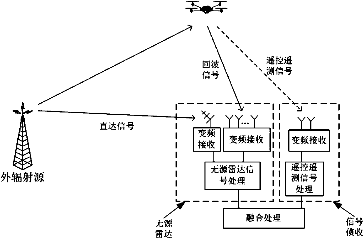
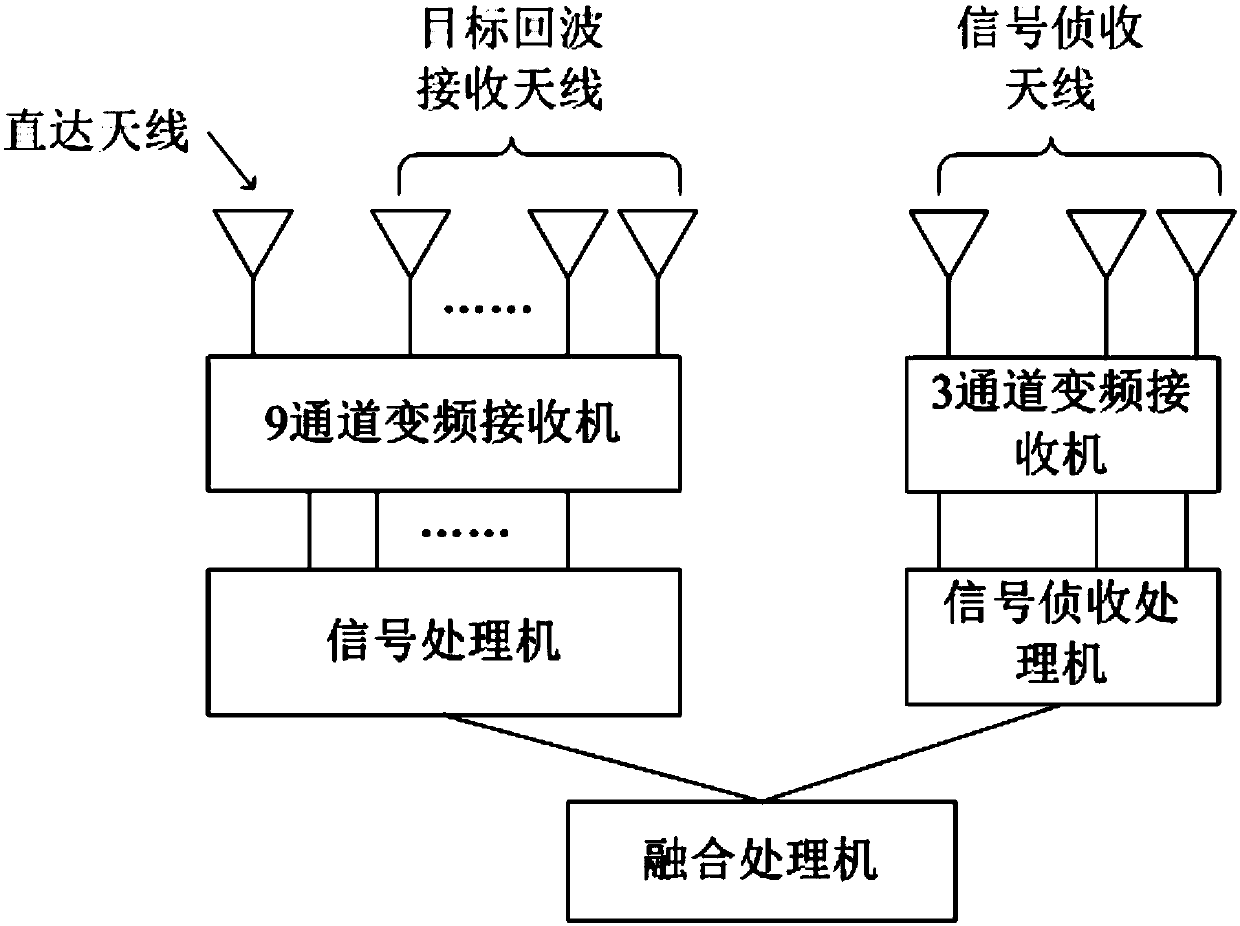
[0026] Passive radar uses analog FM broadcasting stations as the external radiation source, and is mainly composed of three parts: the direct receiving signal receiving part, the target signal receiving part, and the signal processor. The direct signal receiving part is composed of a direct signal receiving antenna with good orientation and a frequency conversion receiver. The target signal receiving part is composed of an 8-unit array antenna and an 8-channel frequency conversion receiver. The signal processor is composed of 9-channel AD acquisition, digital down-conversion and Composed of high-speed digital signal processor. The direct signal and the target echo signal are respectively received by the antenna and converted into a fixed intermediate frequency signal. After the quantitative acquisition is completed by the AD acquisition, it is converted into a digital baseband signal through digital down-conversion. Among them, the multi-channel target echo signal is formed by...
PUM
 Abstract
Description
Claims
Application Information