Ultraviolet LED light source system for ink curing

A technology of LED light source and LED lamp beads, applied in optics, optomechanical equipment, microlithography exposure equipment, etc., can solve the problems of unsatisfactory curing effect, low energy utilization rate, narrow spectrum, etc., to improve the curing effect of ink, Balanced light intensity and high energy efficiency

Pending Publication Date: 2018-02-09
CHONGQING INST OF GREEN & INTELLIGENT TECH CHINESE ACADEMY OF SCI +1
View PDF5 Cites 4 Cited by
  • Summary
  • Abstract
  • Description
  • Claims
  • Application Information

AI Technical Summary

Problems solved by technology

[0002] The ink used in traditional UV curing is matched with the spectrum of the mercury lamp. The wavelength of the LED lamp bead is relatively single and the spectrum is very narrow. Therefore, how to replace the traditional mercury lamp with a suitable ratio of UV LEDs with multiple bands to achieve good curing The effect of traditional UV ink has become an important subject of research by those skilled in the art
However, the use of LED light sources for ink curing has the following difficulties: 1. The ink used in traditional UV curing is matched with the spectrum of mercury lamps. LEDs are used to replace traditional mercury lamps. Due to the difference in spectrum between LEDs and mercury lamps, the curing effect is often not ideal. Exposure process is difficult to be compatible
2. Most of the existing ink curing devices do not use a secondary light distribution lens. It is difficult to achieve a balance between the uniformity of the light spot on the target surface and the energy utilization rate. Especially, most of the LED light at the edge is outside the target surface, and the energy utilization rate is very low. Low

Method used


Image

  • Ultraviolet LED light source system for ink curing
  • Ultraviolet LED light source system for ink curing
  • Ultraviolet LED light source system for ink curing

Examples


Embodiment Construction

[0021] The present invention will be described in further detail below through specific examples.

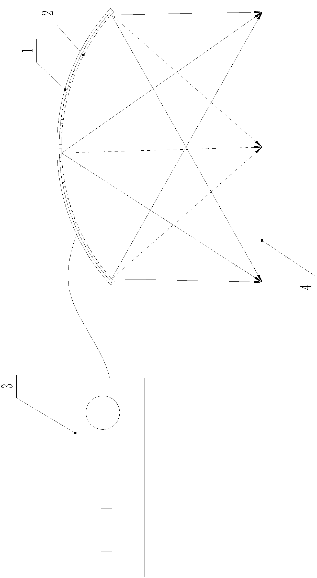
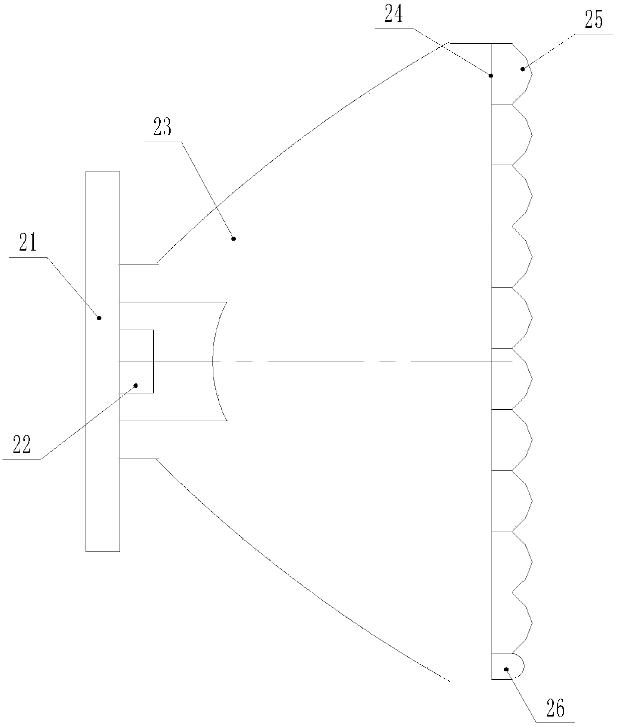
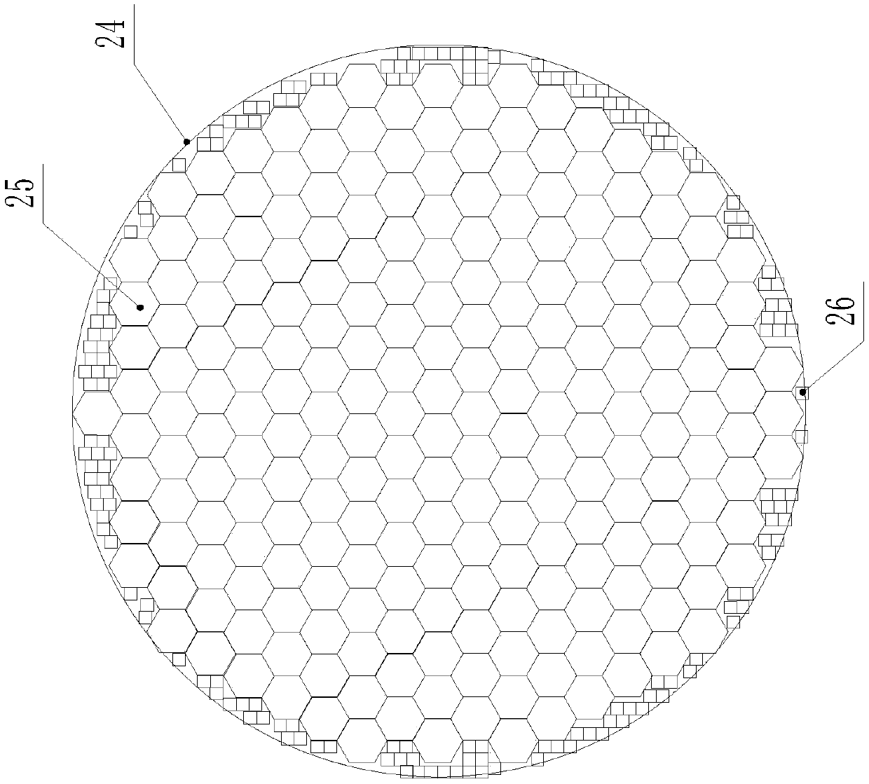
[0022] Such as Figure 1 to Figure 5 As shown, an ultraviolet LED light source system for ink curing includes an LED power supply control box 3 and an ultraviolet LED light source light output head electrically connected to the power control box 3. The ultraviolet LED light source light output head includes a spherical fixed plate 1, and the An ultraviolet LED array is fixed on the inner side of the spherical surface fixing plate 1, and the center of the irradiated target surface 4 coincides with the spherical center of the spherical surface fixing plate 1, and the ultraviolet LED array includes a plurality of LED lamps emitting ultraviolet light of different wavelengths Bead assembly 2, each LED lamp bead assembly 2 is alternately arranged on the spherical fixed plate 1, each LED lamp bead assembly 2 includes a substrate 21 and an LED lamp bead 22 fixed on the substrate 21, the...


PUM


Abstract

The invention discloses an ultraviolet LED light source system for ink curing. The ultraviolet LED light source system comprises an LED power supply control box and an ultraviolet LED light source outlet head, wherein the ultraviolet LED light source outlet head comprises a spherical surface fixing plate, an ultraviolet LED array is fixedly arranged on an inner side surface of the spherical surface fixing plate and comprises a plurality of LED bead assemblies, the plurality of LED bead assemblies are used for emitting ultraviolet light with different wavelengths, the LED bead assemblies are alternatively arranged on the spherical surface fixing plate, each LED bead assembly comprises a substrate and an LED bead, a collimating lens is fixedly arranged on the substrate and covers the LED bead, a light emergent surface of the collimating lens is in a round shape, a plurality of microlens are arranged on the light emergent surface, the microlens and the collimating lens are integratedly formed, the microlens are closely adjacent to one another, and the power supply control box is used for controlling each LED bead to output according to different output powers. By the light source system, the ink curing requirement can be met by employing LED lighting, so that the uniformity of light rays at an edge of a target surface is improved.

Description

technical field [0001] The invention relates to an ultraviolet LED light source system for ink curing, belonging to the technical field of ultraviolet exposure lighting for exposure machines. Background technique [0002] The ink used in traditional UV curing is matched with the spectrum of the mercury lamp. The wavelength of the LED lamp bead is relatively single and the spectrum is very narrow. Therefore, how to replace the traditional mercury lamp with a suitable ratio of UV LEDs with multiple bands to achieve good curing The effect of traditional UV inks has become an important subject of research by those skilled in the art. However, the use of LED light sources for ink curing has the following difficulties: 1. The ink used in traditional UV curing is matched with the spectrum of mercury lamps. LEDs are used to replace traditional mercury lamps. Due to the difference in spectrum between LEDs and mercury lamps, the curing effect is often not ideal. The exposure process ...

Claims


Application Information

Patent Timeline
Patent Type & Authority Applications(China)
IPC IPC(8): G03F7/20
CPCG03F7/20G03F7/70008G03F7/7015
Inventor 江海波尹韶云孙秀辉谭艾英杨若夫陈建军
Owner CHONGQING INST OF GREEN & INTELLIGENT TECH CHINESE ACADEMY OF SCI
Why Eureka
Try Eureka