Supercharge Your Innovation With Domain-Expert AI Agents!

A low-profile magnetoelectric dipole antenna based on a bent magnetic wall

A technology of dipole antenna and electric dipole is applied in the direction of resonant antenna, antenna grounding device, antenna grounding switch structure connection, etc., to achieve the effects of easy module integration, increased equivalent length, and simple processing

Active Publication Date: 2020-01-31
BEIJING UNIV OF POSTS & TELECOMM
View PDF5 Cites 0 Cited by
  • Summary
  • Abstract
  • Description
  • Claims
  • Application Information

AI Technical Summary

Problems solved by technology

[0005] The characteristics of magnetoelectric dipoles are suitable for precise indoor positioning research, but at present, magnetoelectric dipoles still need to be improved for the characteristics of lightness, simplicity, and easy integration.

Method used


Image

  • A low-profile magnetoelectric dipole antenna based on a bent magnetic wall
  • A low-profile magnetoelectric dipole antenna based on a bent magnetic wall
  • A low-profile magnetoelectric dipole antenna based on a bent magnetic wall

Examples


Embodiment

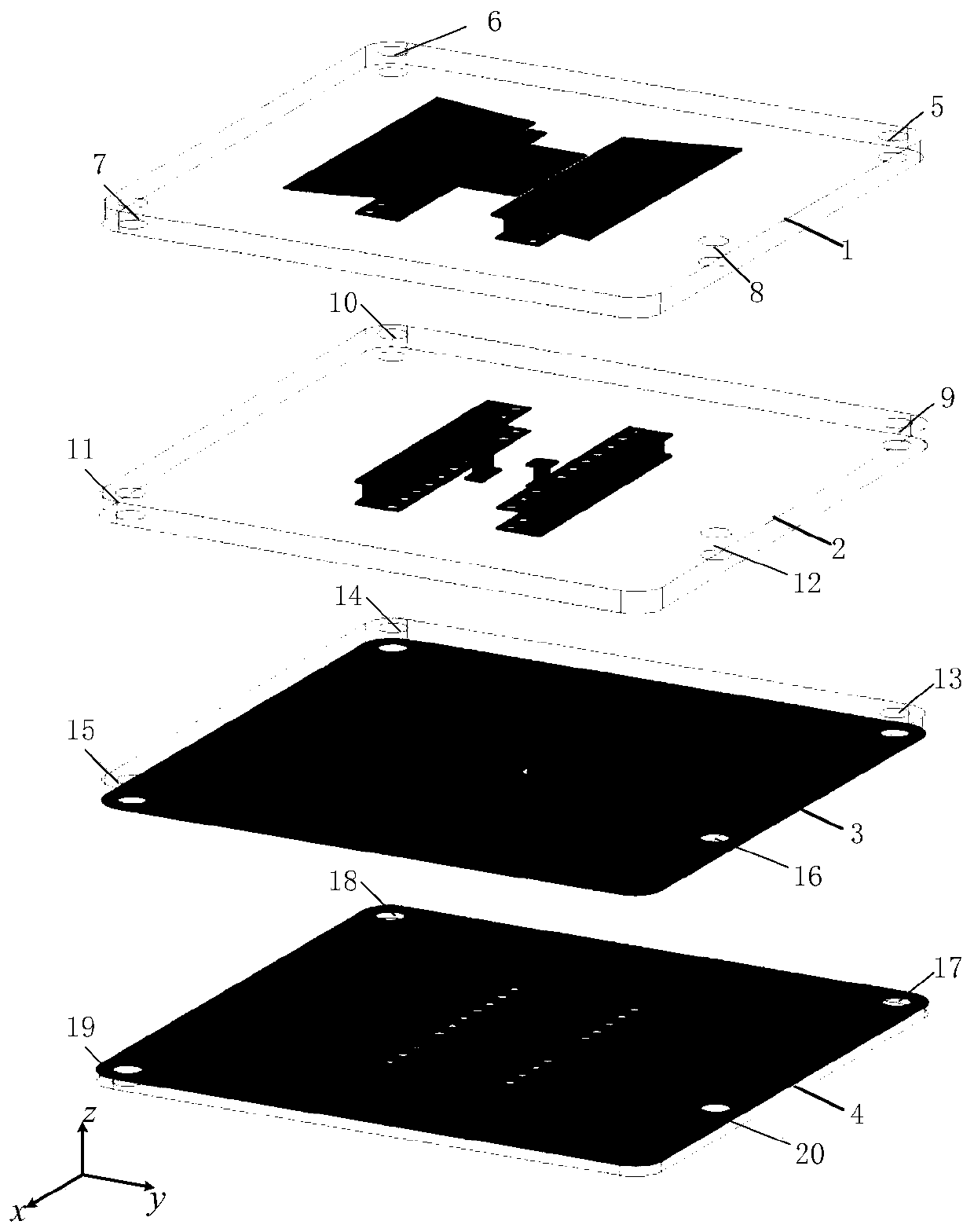
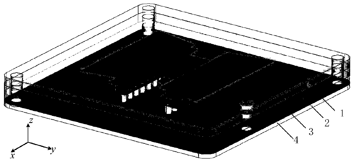
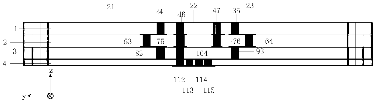
[0030] The low-profile magnetoelectric dipole antenna based on the bending magnetic wall of the present invention reduces the antenna section by bending the magnetic wall. Antenna structure diagram see Figure 1-8 , figure 1 shows the layered structure of the antenna, figure 2 shows the overall diagram of the antenna, image 3 shows the overall front view of the antenna, Figure 4-7 Schematic diagrams of 1-4 layer dielectric substrates are shown respectively. Figure 8 A block diagram of a common ground coplanar waveguide for an antenna feed unit is shown.

[0031] A low-profile magnetoelectric dipole antenna based on a bent magnetic wall of the present invention includes a radiating unit part, a "Γ"-shaped feeding part and a common-ground coplanar waveguide feeding part (ie, GCPW feeding). The radiation unit part includes a pair of trapezoidal electric dipoles and short-circuit bent magnetic dipoles, wherein the short-circuit bent magnetic dipoles are composed of two co...


PUM

PropertyMeasurementUnit
thicknessaaaaaaaaaa
thicknessaaaaaaaaaa

Abstract

The invention discloses a low-profile magnetoelectric dipole antenna structure based on a bent magnetic wall, and the structure comprises a radiation unit part and a vertically-inverted-L-shaped feedpart and a common-ground coplanar waveguide feed part. The radiation unit part comprises a pair of trapezoidal electric dipoles and a pair of short-circuit bent magnetic dipoles, wherein the electricdipole are horizontally placed a top dielectric substrate, and the magnetic dipoles are implemented through the forming of metalized via holes on the dielectric substrate. The magnetic dipoles and theelectric dipoles are placed in a mutually perpendicular manner. A horizontal part of the vertically-inverted-L-shaped feed part is a cap-shaped paster, and a vertical part of the vertically-inverted-L-shaped feed part is implemented through the form of metalized via holes. The common-ground coplanar waveguide feed part is located on a bottom dielectric substrate, wherein the upper surface of thedielectric substrate is a metal ground, and the lower surface of the dielectric substrate is provided with two parts: a signal line of a common-ground coplanar waveguide and a ground line. The upper and lower metal grounds are connected with the metalized via holes. The antenna is simple in structure, is easy to integrate, is high in stability, is low in profile, and is suitable for a mobile positioning system in a modern wireless communication system.

Description

technical field [0001] The invention relates to the field of UWB positioning and ranging, in particular to a low-profile magnetoelectric dipole antenna based on a bent magnetic wall. Background technique [0002] Indoor positioning technology is a technical extension of outdoor positioning technology for different application scenarios. At present, with the advancement of application scenarios and increasing demand, indoor positioning technology has gradually entered the public eye. For the accuracy of indoor positioning, centimeter-level positioning technology led by UWB positioning technology has been marketed, and the use of indoor positioning technology is becoming more and more obvious. [0003] The application fields of indoor positioning technology involve all aspects. In the popular VR technology developed in recent years, it is applied to the two-dimensional positioning or three-dimensional positioning of VR theme game parks. The positioning accuracy of 10cm has b...

Claims


Application Information

Patent Timeline
Patent Type & Authority Patents(China)
IPC IPC(8): H01Q1/38H01Q1/48H01Q1/50H01Q9/16
CPCH01Q1/38H01Q1/48H01Q1/50H01Q9/16
Inventor 李秀萍朱华宋佳李全平
Owner BEIJING UNIV OF POSTS & TELECOMM
Features
  • R&D
  • Intellectual Property
  • Life Sciences
  • Materials
  • Tech Scout
  • Unparalleled Data Quality
  • Higher Quality Content
  • 60% Fewer Hallucinations
Learn More