Eureka AIR delivers breakthrough ideas for toughest innovation challenges, trusted by R&D personnel around the world.

Phase change failure prevention method based on rectification side trigger angle emergency control

A technology of commutation failure and prevention method, applied in the direction of power transmission AC network, etc., can solve the problems of DC current rise, slow start, limited prevention ability of commutation failure, etc.

Active Publication Date: 2018-02-09
STATE GRID HENAN ELECTRIC POWER ELECTRIC POWER SCI RES INST +2
View PDF6 Cites 6 Cited by
  • Summary
  • Abstract
  • Description
  • Claims
  • Application Information

AI Technical Summary

Problems solved by technology

However, at the same time as the DC current predictive control action, the commutation failure predictive control module of the DC control system will reduce the firing angle of the inverter side, thereby making the DC current have a certain upward trend
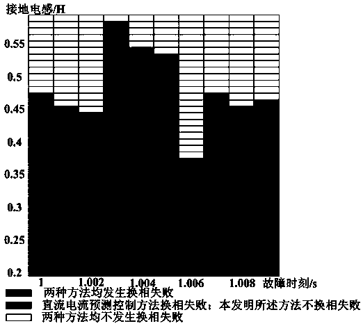
Therefore, there is a certain internal conflict relationship between the DC current predictive control method and the commutation failure predictive control. When these two methods are used at the same time, the control effect of each other will be weakened in a short period of time after the AC system fault occurs, and then reflected in the DC system. The effect of current predictive control is slow; in addition, the starting time of the existing DC current predictive control is completely dependent on the commutation failure predictive control, and the start is slow, so the ability to prevent commutation failure is limited

Method used


Image

  • Phase change failure prevention method based on rectification side trigger angle emergency control
  • Phase change failure prevention method based on rectification side trigger angle emergency control
  • Phase change failure prevention method based on rectification side trigger angle emergency control

Examples


Embodiment Construction

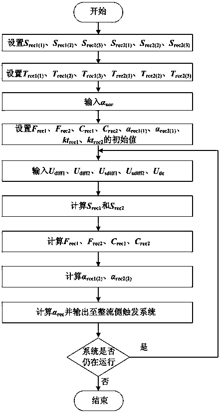
[0068] Such as figure 1 As shown, a commutation failure prevention method for emergency control of firing angle on the rectifier side includes the following steps:

[0069] A: According to the parameters and operating conditions of the DC transmission system and the AC systems connected on both sides, set the starting threshold selection set {S rec1(1) , S rec1(2) , S rec1(3)}, set the starting threshold selection set {S rec2(1) , S rec2(2) , S rec2(3)}, and guarantee S rec1(1) >S rec1(3) >S rec1(2) , S rec2(1) >S rec2(3) >S rec2(2) ;

[0070] The starting threshold selection set must be set experimentally according to the parameters of the DC transmission system and the AC system connected on both sides, and ensure that S rec1(1) >S rec1(3) >S rec1(2) , S rec2(1) >S rec2(3) >S rec2(2) . The starting threshold selection set enables the starting threshold of the emergency hysteresis trigger control method on the rectification side to be changed according to th...


PUM


Abstract

The invention discloses a phase change failure prevention method based on rectification side trigger angle emergency control. Occurrence of phase change failure has a unique correspondence relationship with the rectification side trigger angle and the inversion side trigger angle when the DC system primary parameter and the control system and AC system voltage are certain under the premise of reasonable assumption according to mechanism analysis of phase change, and the rectification side trigger angle and the inversion side trigger angle have no coupling relationship so that the possibility of phase change failure can be rapidly reduced by changing the rectification side trigger angle according to certain logic after the fault occurs in the AC system. The variable fault detection threshold and the variable inertial time constant are adopted, and the rectification side trigger angle is directly controlled without the PI control link so as to have the advantage of rapid response. According to the method, the possibility of phase change failure can be reduced and safe and stable operation of the AC-DC compound system can be maintained.

Description

technical field [0001] The invention relates to the technical field of power system operation and control, in particular to a commutation failure prevention method based on the emergency control of the firing angle at the rectification side. Background technique [0002] my country is vigorously developing DC transmission technology suitable for long-distance and large-capacity transmission. As more and more DC transmission projects are put into operation, my country's power grid has formed a typical "strong DC and weak AC" structure, which is prone to commutation failures. . [0003] Commutation failure is usually caused by the too small arc extinguishing angle of the converter valve after the AC system failure on the inverter side. Commutation failure will cause drastic changes in DC current, voltage, and power, which will have a huge impact on the AC system. A commutation failure predictive control module is often installed in actual HVDC projects to prevent the occurrenc...

Claims


Application Information

Patent Timeline
IPC IPC(8): H02J3/36
CPCH02J3/36Y02E60/60
Inventor 张振安饶宇飞姚伟刘畅李程昊刘阳方舟王建波田春笋高泽
Owner STATE GRID HENAN ELECTRIC POWER ELECTRIC POWER SCI RES INST
Why Eureka
Eureka Blog
Learn More