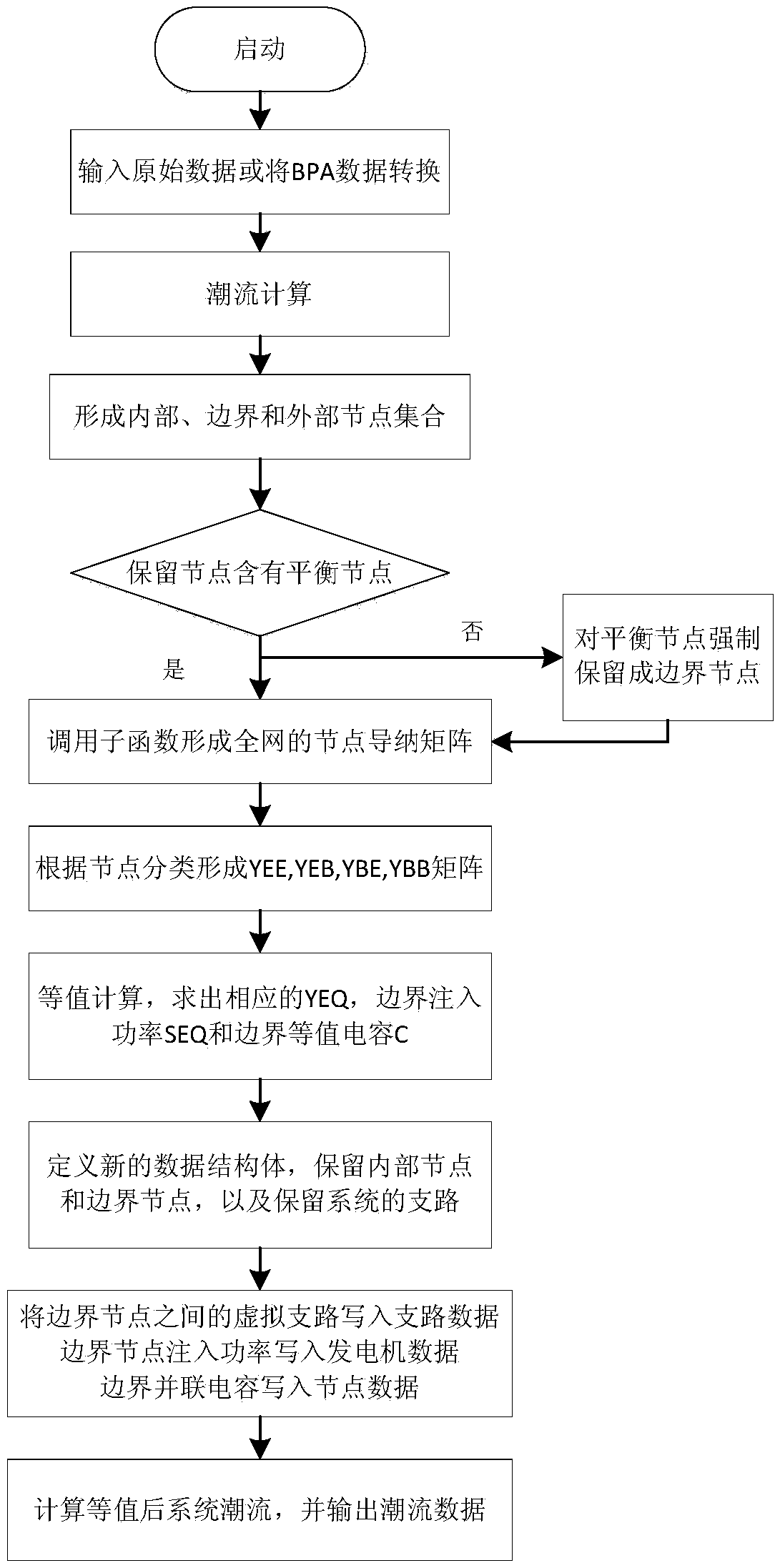
WARD equivalence-based alternating current direct current system equivalence method
A technology of AC and DC systems and equivalent methods, applied in the field of value calculation, can solve problems such as flow evacuation of unfavorable receiving end systems
- Summary
- Abstract
- Description
- Claims
- Application Information
AI Technical Summary
Problems solved by technology
Method used
Image
Examples
Embodiment 1
[0181] (1) IEEE 30-node standard system
[0182] Table 1 presents the detailed results of IEEE-30 node division.
[0183] Table 1 IEEE-30 node division
[0184]
[0185] Apply the equivalent program to the standard 30-node example for equivalent calculation, the boundary equivalent machine (treated as a PQ node), the boundary node virtual branch impedance value, and boundary parallel compensation data are shown in Table 2, Table 3, and Table 4.
[0186] Table 2 Boundary equivalent machine (unit: MW / MVAR)
[0187]
[0188] Table 3 Boundary node virtual branch impedance value (pu.)
[0189]
[0190] Table 4 Boundary parallel compensation value (pu.)
[0191]
[0192] In order to verify the accuracy of the equivalent results, it is necessary to compare the power flows of the pre-equivalent system and the post-equivalent system. In the same operation mode, the power flow calculation is performed on the equivalent system, and the results are shown in Table 5.
[01...
Embodiment 2
[0201] Example 2: 36-node AC-DC hybrid system of China Electric Power Research Institute.
[0202] Taking the 36-node AC-DC hybrid system of China Electric Power Research Institute as an example, the equivalent branch method and the equivalent power source method proposed in this report are used to conduct equivalent analysis on the AC-DC hybrid system.
[0203] (1) Equivalent branch method
[0204] First calculate the power flow for the test system. The AC node power flow results (pu.) on both sides of the DC line are shown in Table 7, where the positive direction is related to Figure 13a , Figure 13b same definition.
[0205] Table 7 Power flow results
[0206]
[0207] Table 7, P 33 and Q 33 represent active power and reactive power injected by node 33 respectively, P 34 and Q 34 Respectively represent the active power and reactive power injected by node 34; V 33 and Respectively represent the node 33 voltage amplitude and phase angle, V 34 and represent ...
PUM
 Abstract
Description
Claims
Application Information
 - R&D
- Intellectual Property
- Life Sciences
- Materials
- Tech Scout
- Unparalleled Data Quality
- Higher Quality Content
- 60% Fewer Hallucinations
Browse by: Latest US Patents, China's latest patents, Technical Efficacy Thesaurus, Application Domain, Technology Topic, Popular Technical Reports.
© 2025 PatSnap. All rights reserved.Legal|Privacy policy|Modern Slavery Act Transparency Statement|Sitemap|About US| Contact US: help@patsnap.com


