Brushless DC motor sensorless rotor position correction method
A brushed DC motor, sensor rotor technology, applied in electronic commutator, torque ripple control and other directions, can solve problems such as system efficiency reduction, motor out-of-step fault, current fluctuation intensification, etc., to improve commutation accuracy and efficiency. , the effect of reducing torque ripple
- Summary
- Abstract
- Description
- Claims
- Application Information
AI Technical Summary
Problems solved by technology
Method used
Image
Examples
specific Embodiment
[0033] Specific embodiments: a sensorless brushless DC motor control system with a working voltage of 30V is used as an object for test verification.
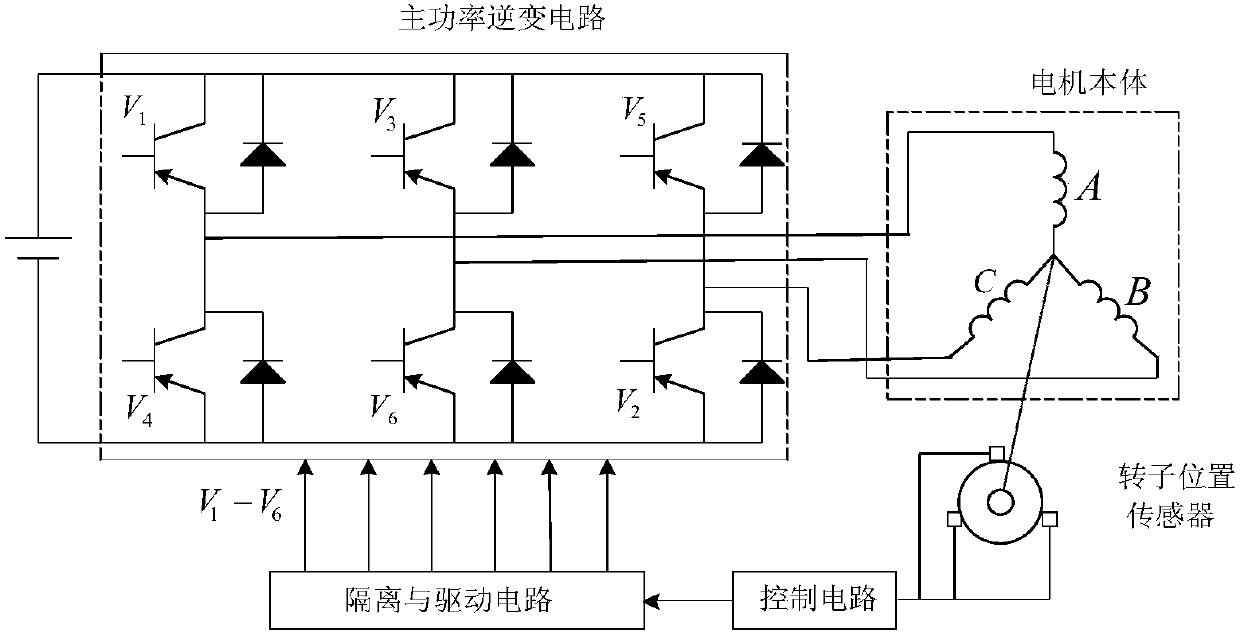
[0034] In the three-phase six-state brushless DC motor bus current detection circuit, the three-phase voltage of the motor is sent to the AD port of the DSP for detection after being filtered and amplified by the voltage sensor. It is especially emphasized that the filtering here only filters out the high-frequency clutter above the chopping frequency.
[0035]The control cycle of the control system software is 25uS (40kHz), the PWM chopping frequency is 15kHz, and the DSP uses TMS320F28335 of TI Company.
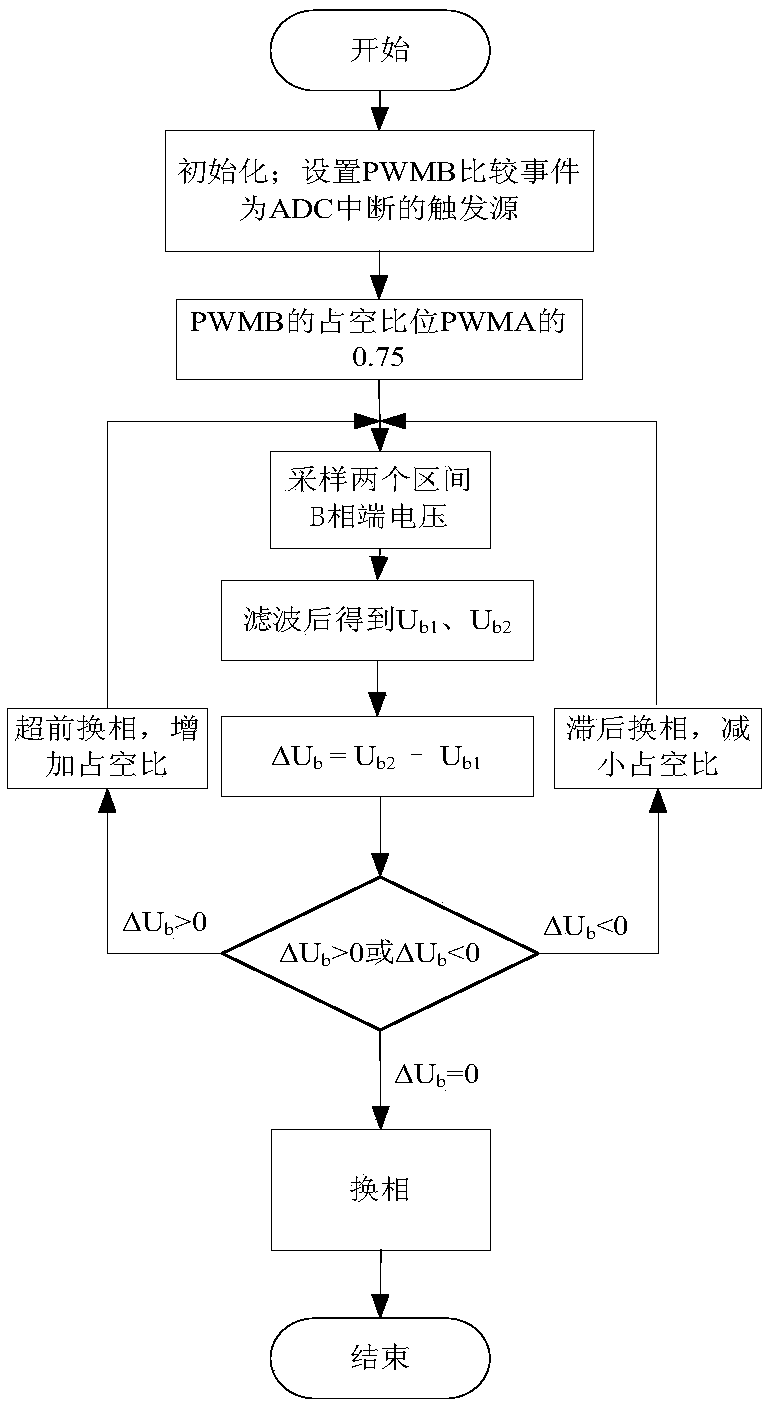
[0036] The specific implementation of zero-crossing sampling and commutation algorithm is according to Figure 4 shown in the flowchart.
[0037] The specific implementation steps of this method are as follows, taking the B-phase terminal voltage as an example:
[0038] Step 1: In the initialization of the system control ...
PUM
 Abstract
Description
Claims
Application Information
 - R&D
- Intellectual Property
- Life Sciences
- Materials
- Tech Scout
- Unparalleled Data Quality
- Higher Quality Content
- 60% Fewer Hallucinations
Browse by: Latest US Patents, China's latest patents, Technical Efficacy Thesaurus, Application Domain, Technology Topic, Popular Technical Reports.
© 2025 PatSnap. All rights reserved.Legal|Privacy policy|Modern Slavery Act Transparency Statement|Sitemap|About US| Contact US: help@patsnap.com


