Full-automatic conveying device for paper rolls

A transmission device, fully automatic technology, applied in the direction of transportation and packaging, conveyors, conveyor objects, etc., can solve the problems of large volume and weight, low work efficiency, inconvenient operation, etc.

Pending Publication Date: 2018-02-13
台山市世昌智能科技有限公司
View PDF0 Cites 1 Cited by
  • Summary
  • Abstract
  • Description
  • Claims
  • Application Information

AI Technical Summary

Problems solved by technology

In the corrugated paper manufacturing workshop, the raw liner paper is generally in the form of a large paper tube. Usually the length of the paper tube is about two meters, and the volume and weight are very large. In small corrugated paper production enterprises, the transportation of the paper tube is usually carried out by manpower. , The labor intensity of the workers is relatively high. In some corrugated paper production enterprises with a certain scale, the paper tubes are transported in the workshop with limited space by forklifts and other equipment. The work efficiency is still low and the operation is inconvenient; some enterprises use conveyor belts and other equipment. To transport the paper tube, but the paper tube loading still needs manual operation, and the conveyor belt cannot change the transmission direction according to the actual needs during the transmission of the paper tube
In short, under the existing technology, the transmission of paper tubes in the workshop still relies more on manual operation. Under the background of the increasing automation of modern enterprises, there is an urgent need for a device that can automatically transport paper tubes

Method used


Image

  • Full-automatic conveying device for paper rolls
  • Full-automatic conveying device for paper rolls
  • Full-automatic conveying device for paper rolls

Examples


Embodiment Construction

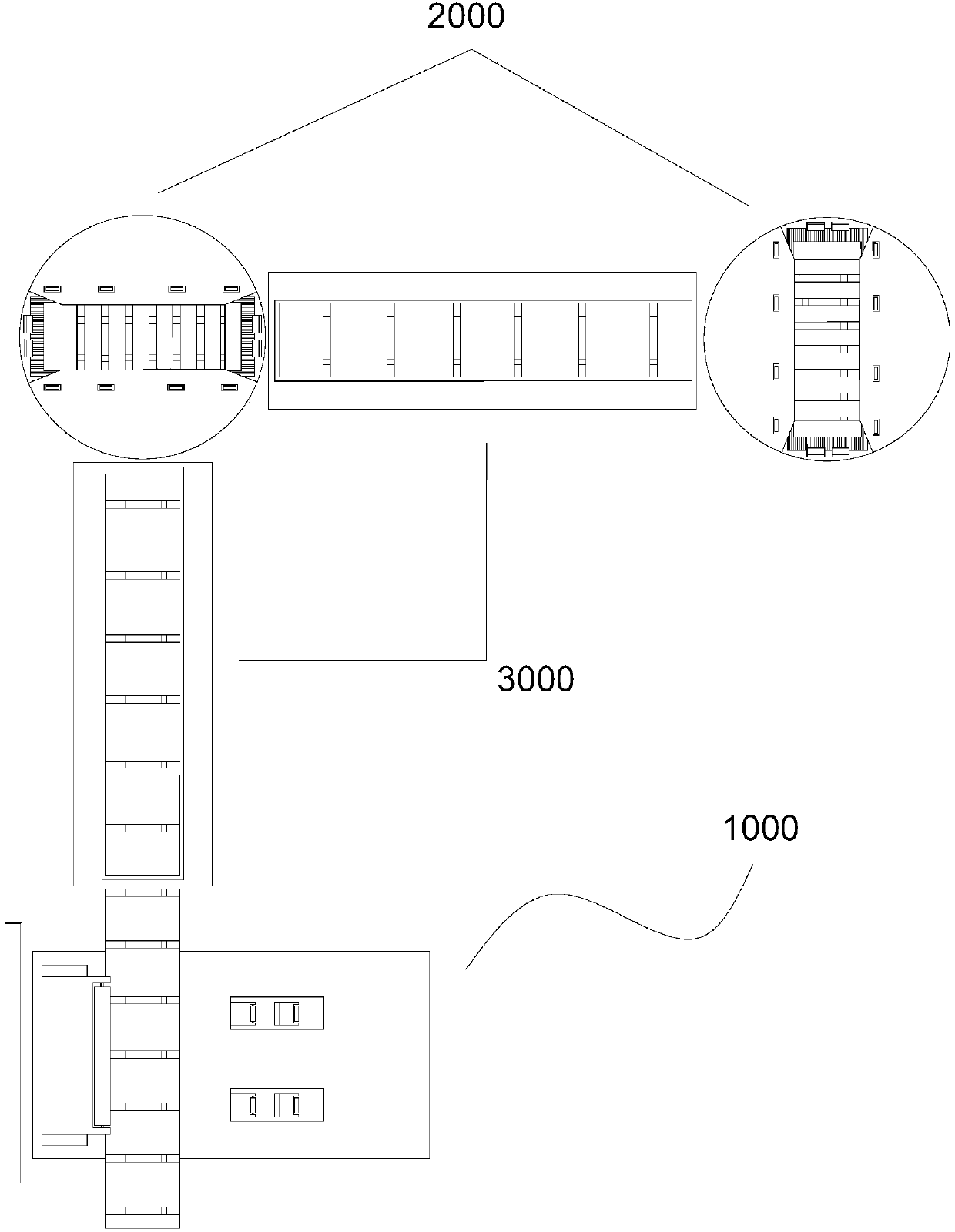
[0031] see figure 1 , a fully automatic paper tube transmission device, which includes: an automatic feeding part 1000, a direction changing transfer part 2000, and two adjacent direction changing transfer parts arranged between the automatic feeding part 1000 and the changing direction transfer part 2000 2,000 between 3,000 and 3,000 bridges. The automatic feeding part 1000, the direction changing transfer part 2000 and the bridge conveyor belt 3000 are all electrically connected with the circuit control system, and their actions are controlled by the circuit control system.

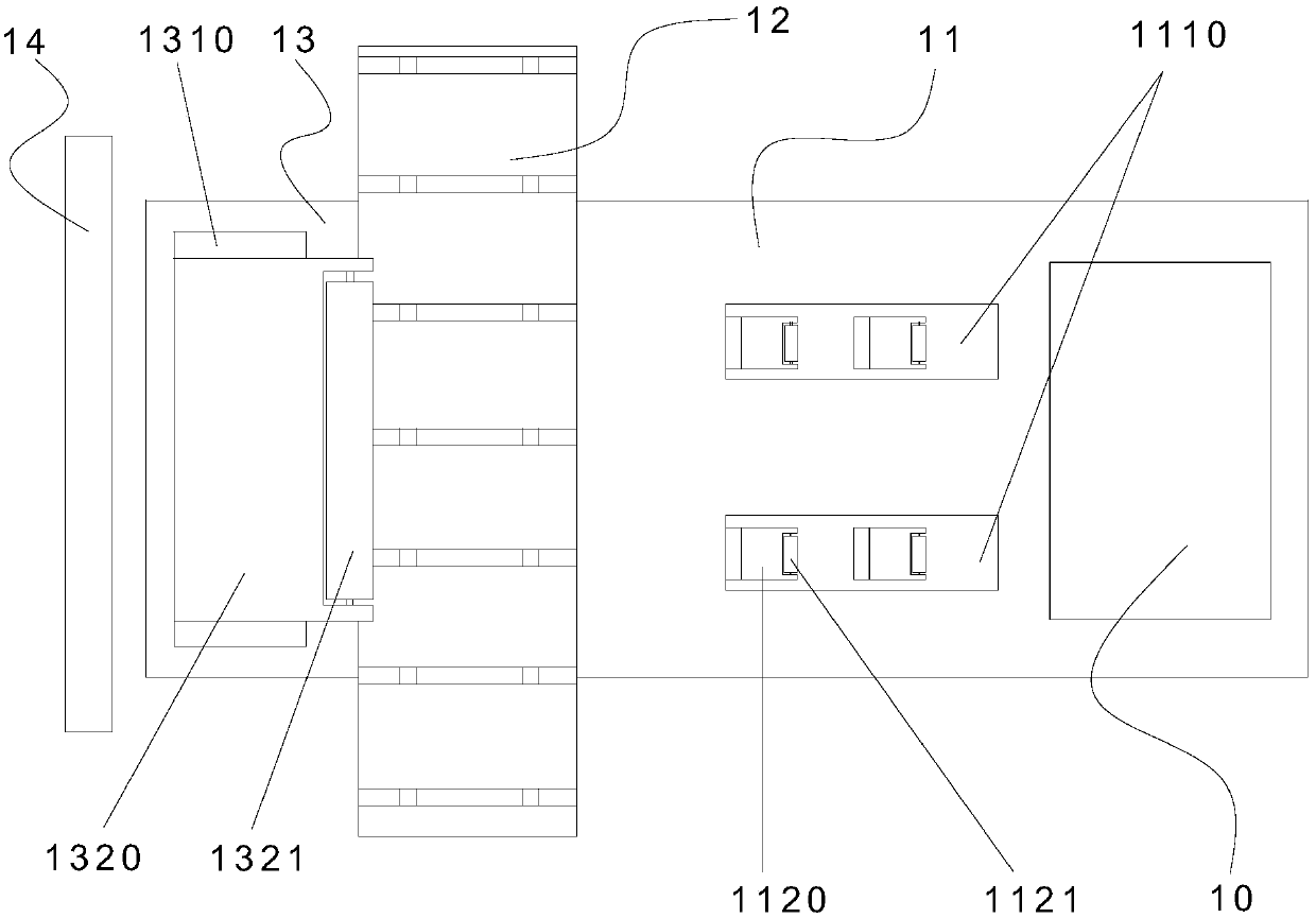
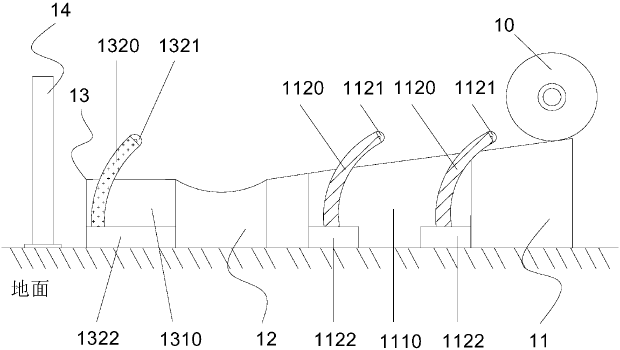
[0032] see figure 2 and image 3 , the automatic feeding part 1000 includes: the ramp plate 11 for discharging the paper tube 10, the upper end surface of which is provided with an opening 1110, and a retractable baffle 1120 is arranged in the opening 1110; the conveyor belt 12 is arranged on the ramp plate 11 Bottom and one side are adjacent to the slope plate 11; platform 13, which is arranged on ...


PUM


Abstract

The invention discloses a full-automatic conveying device for paper rolls. The full-automatic conveying device comprises an automatic feeding part, turning transmission parts, a bridge conveying beltand a circuit control system. The automatic feeding part comprises a slope plate used for discharging the paper rolls, a conveying belt and a platform, wherein a first opening is formed in the slope plate, and a first baffle which can stretch and retract is arranged in the first opening; the conveying belt is arranged at the bottom end of the slope plate in the direction perpendicular to the slopeplate, and one side of the conveying belt is adjacent to the slope plate; and the platform is arranged on the other side of the conveying belt, a second opening is formed in the platform, and a second baffle which can stretch and retract is arranged in the second opening. Each turning transmission part comprises a rotary table, a motor and an annular transmission belt, wherein a strip-shaped opening is formed in the rotary table, the motor is connected with the rotary table, and the annular transmission belt is arranged in the strip-shaped opening. The bridge conveying belt is arranged between the conveying belt and the turning transmission part or between two adjacent turning transmission parts. The circuit control system is electrically connected with the automatic feeding part, the turning transmission parts and the bridge conveying belt. The full-automatic conveying device for the paper rolls is reasonable in structure and can convey the paper rolls fully automatically.

Description

technical field [0001] The invention relates to the technical field of conveying devices, in particular to a fully automatic paper tube conveying device. Background technique [0002] Corrugated paper is a plate made of liner paper and corrugated corrugated paper formed by processing corrugated sticks. It is widely used in paper packaging industries such as carton manufacturing. In the corrugated paper manufacturing workshop, the raw liner paper is generally in the form of a large paper tube. Usually the length of the paper tube is about two meters, and the volume and weight are very large. In small corrugated paper production enterprises, the transportation of the paper tube is usually carried out by manpower. , The labor intensity of the workers is relatively high. In some corrugated paper production enterprises with a certain scale, the paper tubes are transported in the workshop with limited space by forklifts and other equipment. The work efficiency is still low and the...

Claims


Application Information

Patent Timeline
IPC IPC(8): B65G47/64B65G47/06
CPCB65G47/06B65G47/64B65G2203/0266
Inventor 劳保母
Owner 台山市世昌智能科技有限公司
Why Eureka
Try Eureka