Powder-feeding type electronic beam additive manufacturing device arranged in front

A technology of additive manufacturing and electron beam, which is applied in the field of front-end powder-feeding electron beam additive manufacturing device, can solve the problem of low powder utilization rate, achieve the effect of improving utilization rate, avoiding waste, and eliminating influence

Active Publication Date: 2018-02-16
黑龙江省工研院资产经营管理有限公司
View PDF3 Cites 4 Cited by
  • Summary
  • Abstract
  • Description
  • Claims
  • Application Information

AI Technical Summary

Problems solved by technology

[0004] In order to solve the problem that the existing electron beam selective melting additive manufacturing method is only applicable to the additive manufacturing o...

Method used


Image

  • Powder-feeding type electronic beam additive manufacturing device arranged in front

Examples


specific Embodiment approach 1

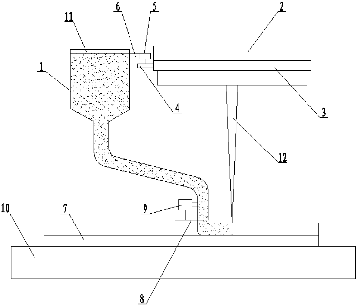
[0011] Specific implementation mode one: combine figure 1 Describe this embodiment, this embodiment includes funnel 1, electron gun 2, annular fixed gear guide rail 3, rotating gear 4, servo motor 5, servo motor bracket 6, flow adjustment damper 8 and damper adjustment motor 9, annular fixed gear guide rail 3 is fixedly installed on the shell of the electron gun 2, the rotating gear 4 meshes with the annular fixed gear guide rail 3, the rotating gear 4 is fixed on the output shaft of the servo motor 5, and the servo motor 5 is fixed to the shell of the funnel 1 through the servo motor bracket 6 Then, the outlet of the funnel 1 is vertically facing the upper surface of the substrate 10, the flow regulating flap 8 is arranged at the outlet position of the funnel 1, the flow regulating flap 8 is fixed on the output end of the flap adjusting motor 9, and the flap adjusting motor The shell of 9 is fixedly connected with the lower end outer wall of funnel 1.

[0012] The servo moto...

specific Embodiment approach 2

[0016] Specific implementation mode two: combination figure 1 Describe this embodiment, in this embodiment, the cross-sectional shape of the lower mouth of the funnel 1 is square or circular. Other components and connections are the same as those in the first embodiment.

specific Embodiment approach 3

[0017] Specific implementation mode three: combination figure 1 Describe this embodiment, this embodiment is that the shutter adjusting motor 9 is a stepper motor or a servo motor. Such setting can ensure that the position of the shutter can be accurately controlled under the action of the shutter adjusting motor 9, and the shutter adjusting motor 9 must have sufficient torque to ensure that the position of the shutter is not affected by the powder flow. Other compositions and connections are the same as those in Embodiment 1 or 2.


PUM


Abstract

The invention provides a powder-feeding type electronic beam additive manufacturing device arranged in front. The problem that an existing electronic beam selective melting additive manufacturing device is only suitable for additive manufacturing of small precise parts and thus the utilization rate of powder is very low is solved. The powder-feeding type electronic beam additive manufacturing device arranged in front comprises a hopper, an electronic gun, an annular fixing gear guiding rail, a rotating gear, a servo motor, a servo motor support, a sedimentary body, a flow adjusting stop pieceand a stop piece adjusting motor. The annular fixing gear guiding rail is fixedly mounted on a shell of the electronic gun, the rotating gear is engaged with the annular fixing gear guiding rail and fixedly mounted at an output shaft of the servo motor, and the servo motor is fixedly connected with a shell of the hopper through the servo motor support. An outlet of the hopper is perpendicular to the upper surface of a base plate directly facing the outlet, the flow adjusting stop piece is arranged at the outlet of the hopper and fixedly mounted at the output end of the stop piece adjusting motor, and a shell of the stop piece adjusting motor is fixedly connected with the outer wall of the lower end of the hopper. The powder-feeding type electronic beam additive manufacturing device arranged in front is used for electronic beam additive manufacturing.

Description

technical field [0001] The invention relates to an electron beam fuse deposition processing technology, in particular to a pre-powder feeding type electron beam additive manufacturing device. Background technique [0002] In many fields such as aerospace, micro-nano manufacturing, and biomedical engineering, electron beam additive manufacturing technology has been widely used. At present, the commonly used electron beam additive manufacturing methods include electron beam fuse deposition and electron beam selective melting. The principle of electron beam fuse deposition is to melt the wire under the action of the heat source of the electron beam and then solidify to form a deposit. Different wire feeding directions and angles have a great influence on the shape and performance of the deposit, and the wire feeding accuracy is electronic. The key to beam fuse deposition is that once the wire material is thermally deformed or the wire feeding accuracy is affected by the outsid...

Claims


Application Information

Patent Timeline
IPC IPC(8): B29C64/153B29C64/329B29C64/393B22F3/105B33Y40/00B33Y50/02
CPCB33Y40/00B33Y50/02B22F10/00B22F12/52B22F12/226B22F12/57B22F10/25B22F10/37Y02P10/25
Inventor 陈国庆树西柳峻鹏张秉刚冯吉才
Owner 黑龙江省工研院资产经营管理有限公司
Why Eureka
Try Eureka