Rotary drilling device and construction method for drilling pretreatment of cast-in-place piles in sandy soil foundation

A technology of sand foundation and drilling device, applied in drilling equipment and methods, earthwork drilling, infrastructure engineering and other directions, can solve the problems of difficult quality control, complex drilling rig structure, large hole diameter, etc. Ease of operation, increased flexibility, and improved quality results

Active Publication Date: 2019-04-26
ZHEJIANG UNIV OF WATER RESOURCES & ELECTRIC POWER
View PDF5 Cites 0 Cited by
  • Summary
  • Abstract
  • Description
  • Claims
  • Application Information

AI Technical Summary

Problems solved by technology

Most of the construction of cast-in-situ piles is completed underground or underwater, and there are many construction procedures, which leads to great difficulty in quality control. Compared with positive circulation rotary drilling, reverse circulation rotary drilling can maintain fast hole forming speed, low noise, and small vibration. In addition to the advantages of large hole diameter and high drilling depth, it also has the characteristics of low mud quality requirements, fast hole cleaning speed, and high hole cleaning efficiency. However, the structure of the drilling rig is complicated and the cost is high.

Method used


Image

  • Rotary drilling device and construction method for drilling pretreatment of cast-in-place piles in sandy soil foundation
  • Rotary drilling device and construction method for drilling pretreatment of cast-in-place piles in sandy soil foundation
  • Rotary drilling device and construction method for drilling pretreatment of cast-in-place piles in sandy soil foundation

Examples


Embodiment Construction

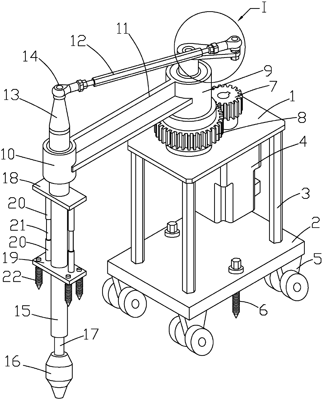
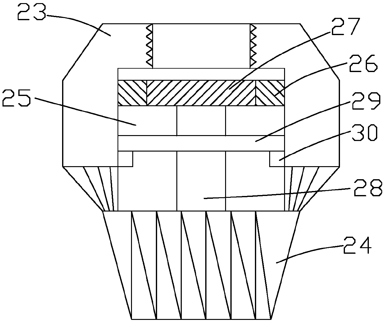
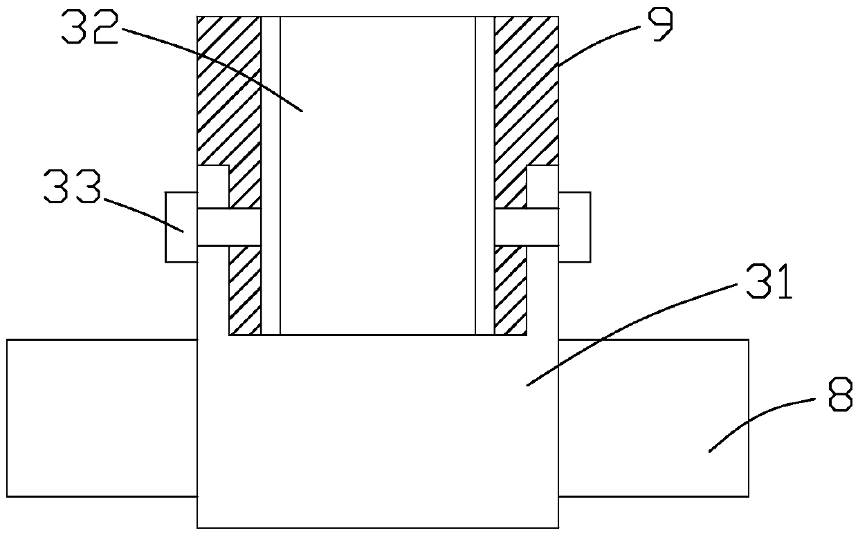
[0042] Such as Figure 1 to Figure 4 As shown, it is a rotary drilling device for drilling pretreatment of cast-in-place piles in sandy soil foundation according to the present invention, including a support platform 1, a bottom plate 2, a driving mechanism, a rotating mechanism, a drilling mechanism and a positioning mechanism, and the support platform 1 is located above the bottom plate 2 , the bottom plate 2 is connected to the support platform 1 through the column 3, the bottom surface of the bottom plate 2 is uniformly provided with a roller assembly 5, the bottom plate 2 is provided with a first anchor rod 6, the first anchor rod 6 is located between the two roller assemblies 5, and is connected with the The two roller assemblies 5 are located on the same straight line. Through the design of the roller assemblies 5, the movement of the rotary drilling device is facilitated, and the flexibility during movement is improved. The first anchor rod 6 is used to fix the bottom p...


PUM


Abstract

The invention discloses a rotary drilling device used for sand foundation cast-in-place pile drilling pretreatment and a construction method of the rotary drilling device. The rotary drilling device comprises a supporting table, a bottom plate, a driving mechanism, a rotary mechanism, a drilling mechanism and a positioning mechanism; the driving mechanism comprises a motor, a driving gear and a driven gear, and the rotary mechanism comprises a first positioning cylinder, a second positioning cylinder, a cantilever, a rotary shaft and a rotary assembly; the first positioning cylinder is connected with the second positioning cylinder through the cantilever and internally provided with a transmission shaft, and the rotary shaft is sleeved with the second positioning cylinder; and the drillingmechanism is connected to the rotary shaft, and the drilling mechanism is sleeved with the positioning mechanism. The construction method of the rotary drilling device comprises the steps of pile positioning measuring and sampling, pile casing embedment, rotary drilling device construction, pile casing earthwork backfilling, pile casing pulling out and rotary drilling device clearing. According to the rotary drilling device, the structure is simple, the manufacturing cost is low, quick positioning can be achieved, the drilling efficiency is improved, and the construction method is simple in step and can achieve pretreatment construction of foundation cast-in-place piles with different soil property requirements.

Description

technical field [0001] The invention relates to a rotary drilling device and a construction method thereof for drilling pretreatment of cast-in-situ piles in sand foundation. Background technique [0002] The cast-in-situ pile is an extremely effective, safe and reliable foundation pile. It has the advantages of transferring the superstructure load to the deep and stable soil layer and greatly reducing the settlement of the foundation. Therefore, it has become a widely used pile foundation in construction projects . Most of the construction of cast-in-situ piles is completed underground or underwater, and there are many construction procedures, which leads to great difficulty in quality control. Compared with positive circulation rotary drilling, reverse circulation rotary drilling can maintain fast hole forming speed, low noise, and small vibration. In addition to the advantages of large hole diameter and high drilling depth, it also has the characteristics of low mud qual...

Claims


Application Information

Patent Timeline
Patent Type & Authority Patents(China)
IPC IPC(8): E21B3/02E21B7/02E21B7/20E02D5/38
CPCE02D5/38E21B3/02E21B7/02E21B7/024E21B7/20
Inventor 刘学应
Owner ZHEJIANG UNIV OF WATER RESOURCES & ELECTRIC POWER
Why Eureka
Try Eureka